




1 Million Creator Fund
RC
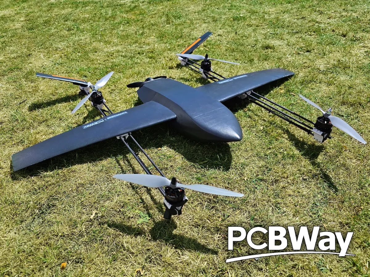
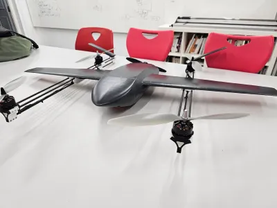
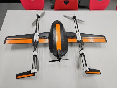
Drone
VTOL
remote
control
plane


231

18
Motors:
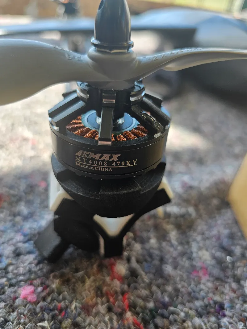
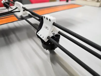
The SLS mounts are designed specifically for this motor as mounting holes are different on most motors. This motor is 470KV and can be found at the following link. Purchase 3 CW and 2 CCW versions.
Propellers
2x CW 12 inch, 2x CCW 12 inch, 1x CW 7 inch.
Camera:
The model is designed for the Axisflying thermal camera. A placeholder can be 3D Printed from PLA or similar and act as a placeholder to fill the hole. Depending on resolution, this camera can range from 220USD to 680USD.
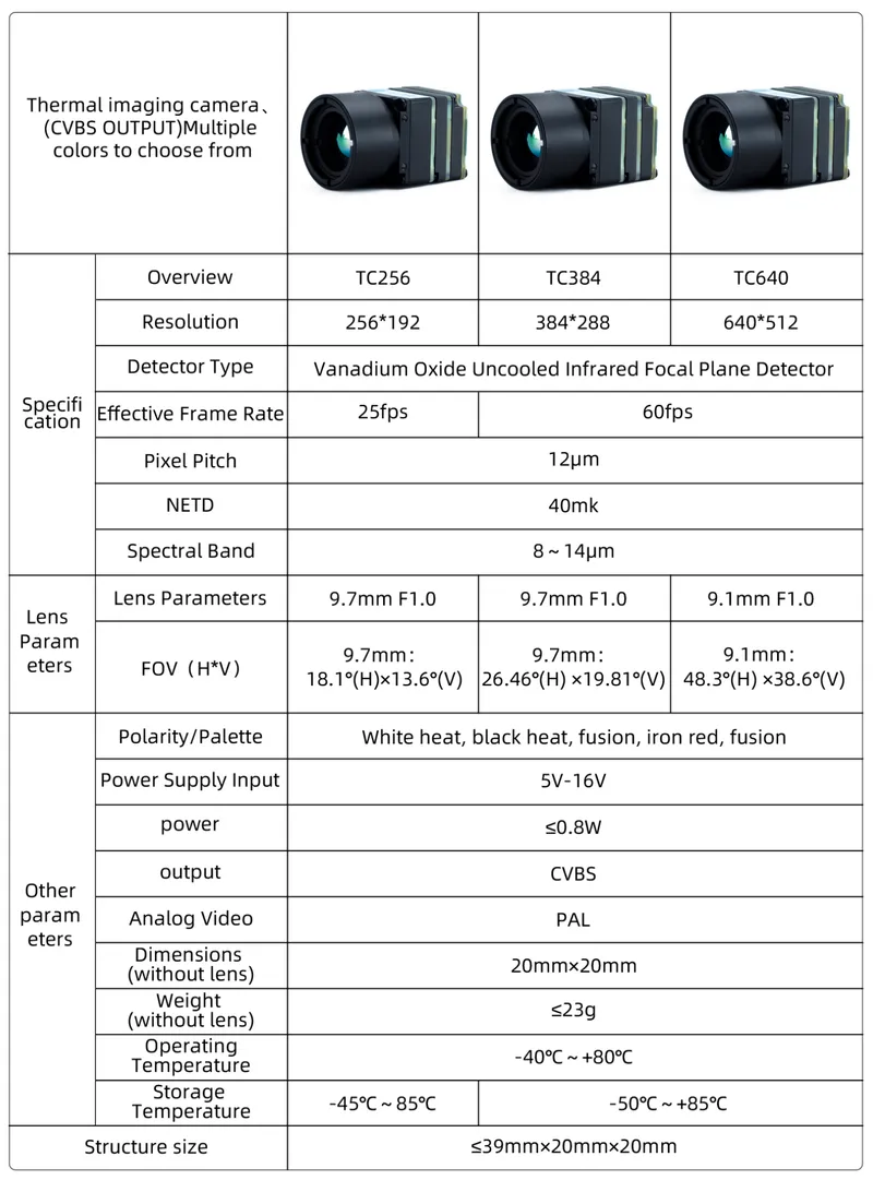
https://grabcad.com/library/axisflying-thermal-fpv-drone-camera-1
Battery:
4S2P battery we used: https://amzn.eu/d/hesU79I
XT90 connector. Remember to get a lipo charger!
I suggest cutting out a connector hole on the bottom of the aircraft and glue on a charging port for quick battery recharging.
SLS Parts:
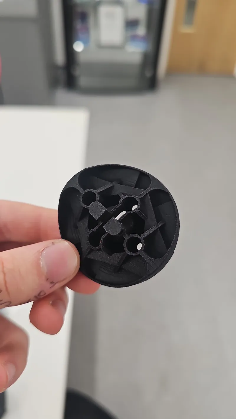
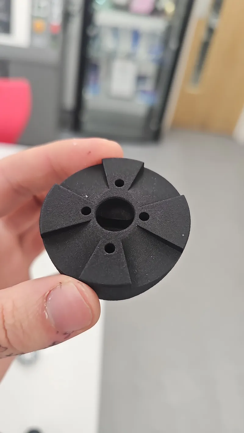
Manufactured from PA12 from 3DPRINTUK with the "shot peen" finish.
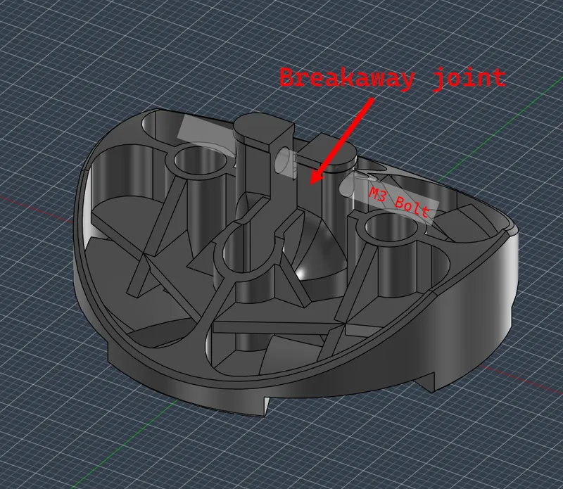
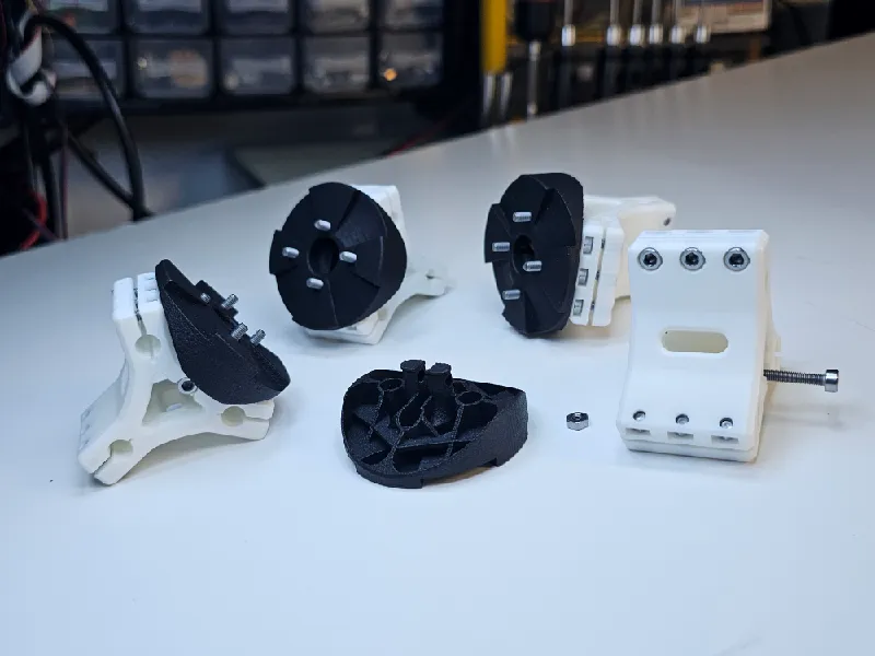
Designed to fit 4 M3 bolts from the bottom to bolt on to the motor. Part optimised for SLS Printing. Also included air channels on the side that touches the motor for better ventilation.
Breakaway points included to prevent CF rods or wings from breaking during malfunctions
ASA Parts:
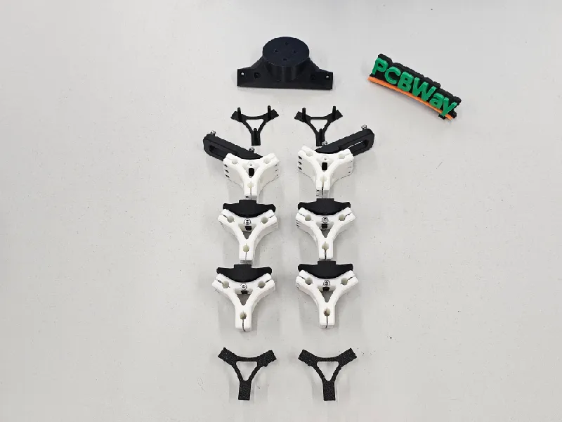
Increase strength as much as possible for “CF Rod Wing Mount” and “CF Rod Modular Connectors”.
Make “Horizontal Motor Mount” slightly stronger than default settings, and the rest can be on default.
PA6 Parts:
The PCB frame/holder was made from Inland PA6 Filament. There is no need for you to use PA6, ASA or PLA is fine.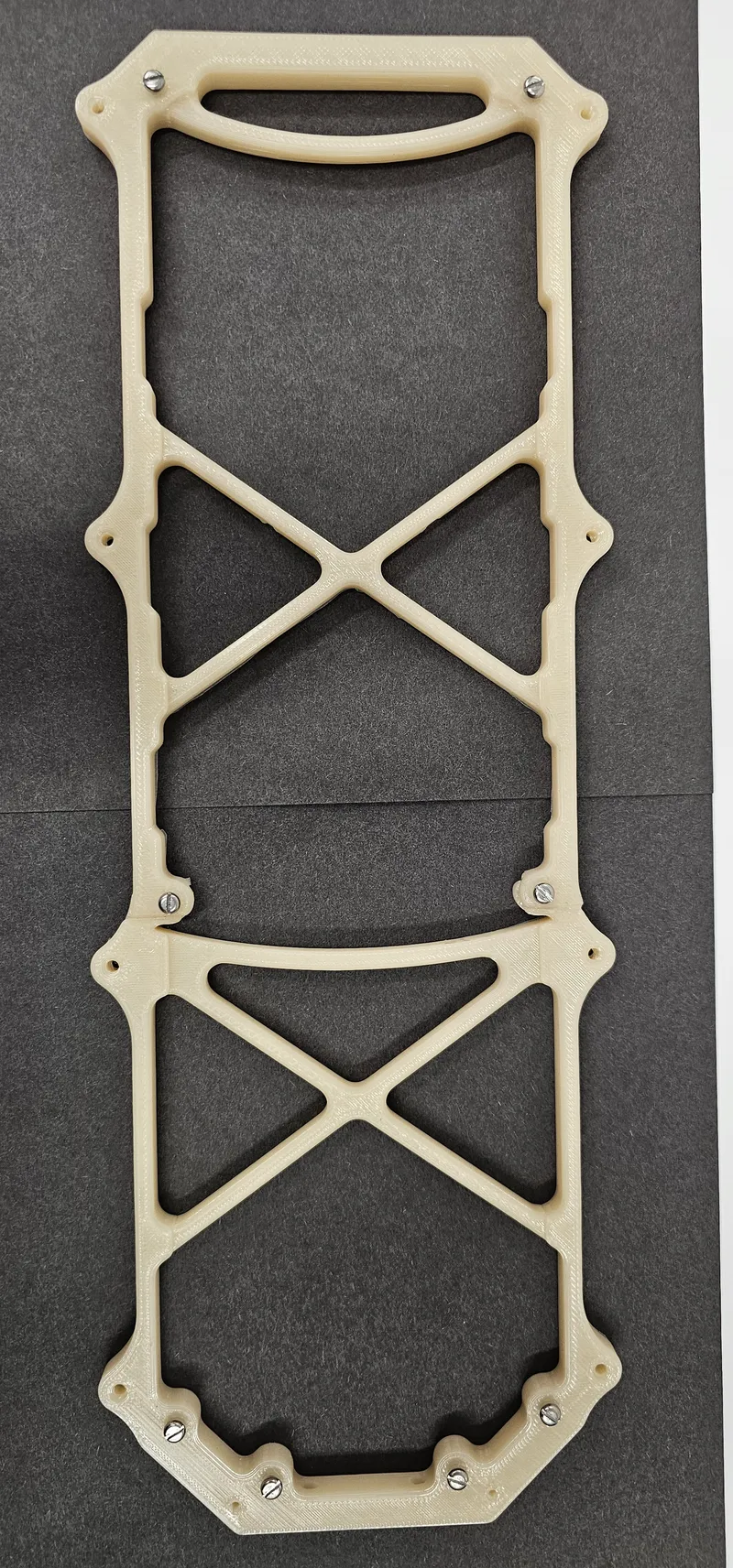
ASA Aero Parts:
3D Printed from Bambulab's ASA Aero:
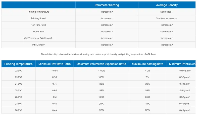
0.6mm nozzle, 2 (max 3) walls, adaptive cubic infill at low %. Printed on the P1S.
Some parts such as Body 1 and Body 3 need supports. Use brims where possible, and use glue stick to prevent wing parts from falling over during printing.
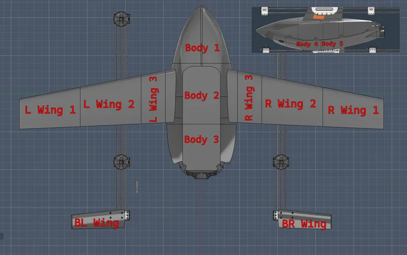
CF Rods:
4mm ID, 6mm OD, 1m length x6
spare CF rods for use in wings. 2x 1m long, cut down to size
Electronics (What we used):
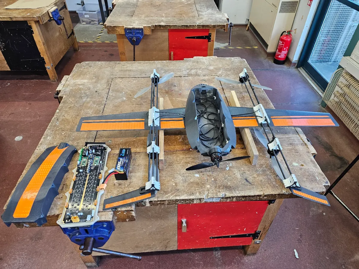
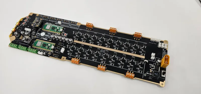
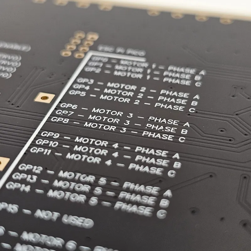
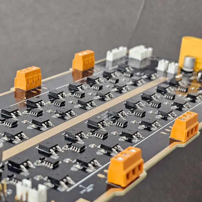
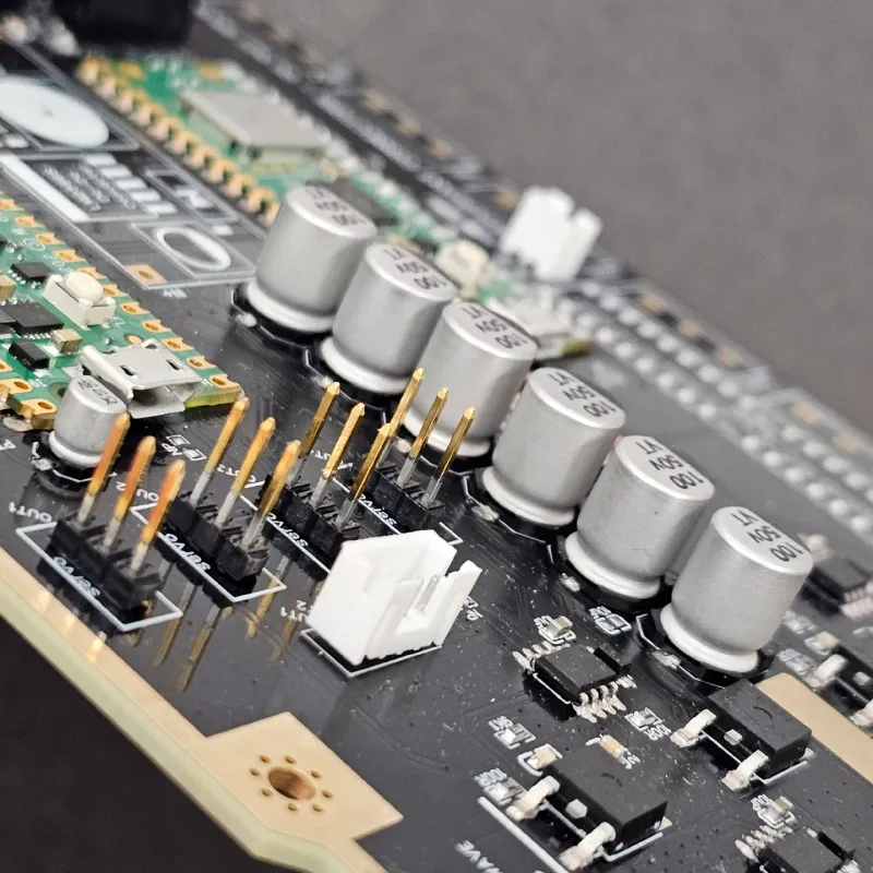
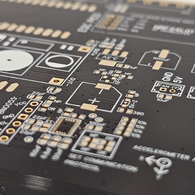
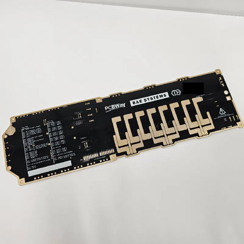
I designed my own flight controller board with integrated ESCs, protection circuitry, a 9-axis acceletometer/gyroscope, etc. This was designed in EasyEDA and manufactured by PCBWay, who is a sponsor of the project.
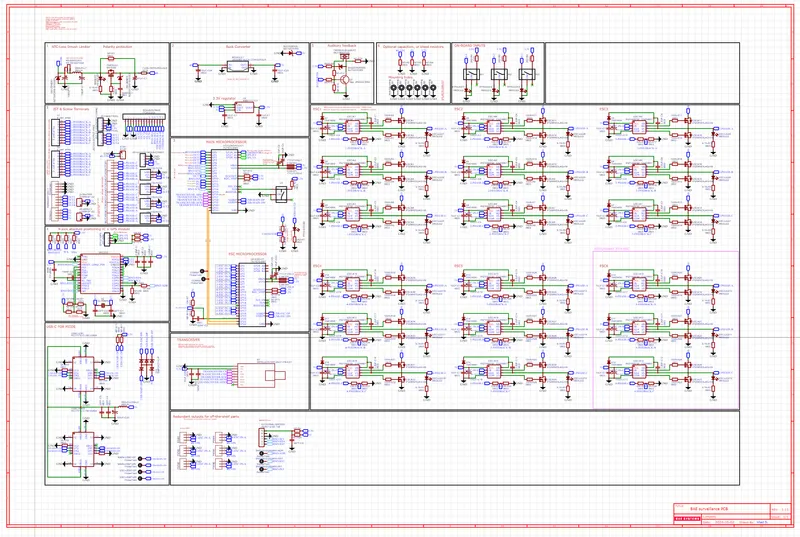
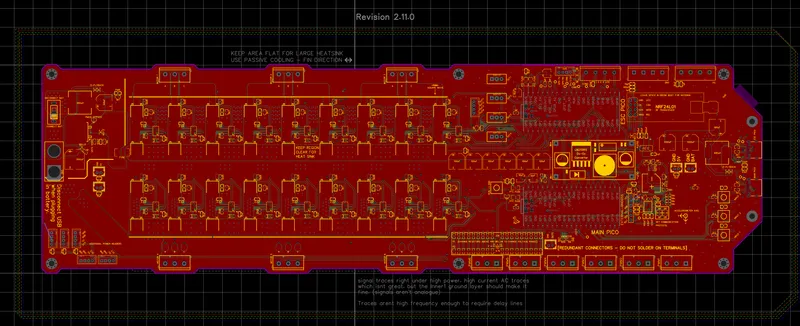
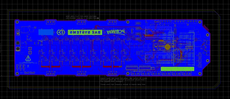
Far left logo covered for privacy. removed entirely in Gerber file.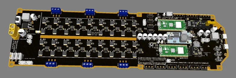
This board cost us £150 in components, and the board itself was approximately £170. For that reason, i suggest you do NOT use this file. The code for the picos was not done by me, but rather another member of the group. While the drone could hover and fly, there were many issues with getting it working properly without drifting, oscillating, or being blown by the wind when in drone mode.
The gerber file is linked below.
PCB Issue:
The MOSFET drivers we originally picked are too slow for the ESCs to work. Please replace with half bridge drivers that have a quicker response and the same pinout.

Electronics (What you can use):
You can use any flight controller and ESC combination, just make sure it can support 5 motors in this configuration. A speedybee f405 Wing is a good option.
Other:
You will need various M3 hex-socket machine screws and nuts. M3 heat-set nuts are also used on the body, and on the tail wings.
I suggest spray painting the model too and using a waterproof clearcoat.
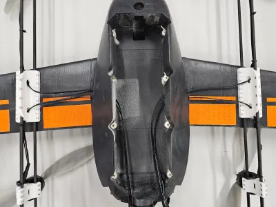
Zipties are used to keep the wires attached to the CF rods, and the motors need to have their wires extended with silicone wire. I suggest https://amzn.eu/d/aMY8DuJ .
You will also need glue (such as PU) to attach the body parts together, along with lightweight filler.
This project was sponsored by PCBWay, who partially helped with the cost. They manufactured the PCB quickly without any issues. I highly encourage you use their service. They also offer 3D Printing and CNC machining.
PCBWay is not only a service for quick and cheap PCB prototyping, but also offer advanced PCB manufacturing for professional and industrial uses. I have used their products for a long time, and have had no problems with their manufacturing (only issues from my own mistakes lol).
Unlike similar services, 3D Printing and PCB files are reviewed before payment instead of after. This makes the payment process much smoother as design issues are spotted, and the price is adjusted before the purchase.
https://www.pcbway.com/

We will continue developing the drone, and changes will be added here.
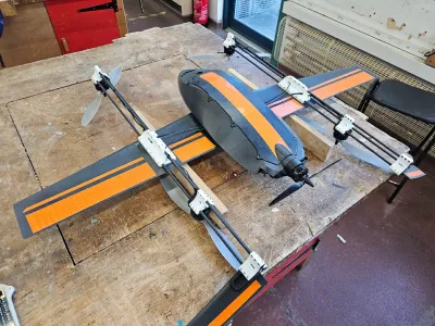
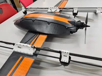
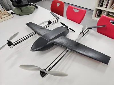
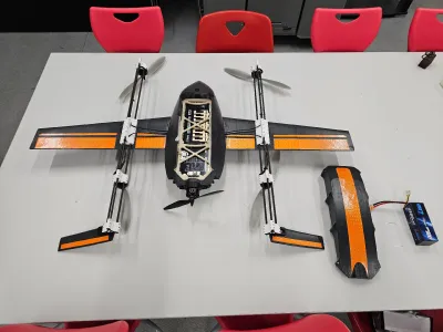
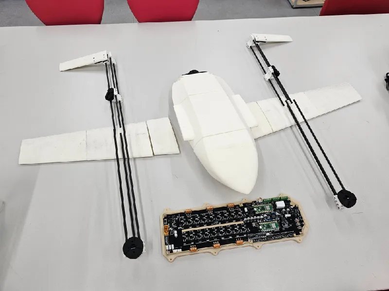
Some production photos:
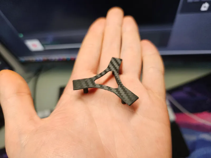
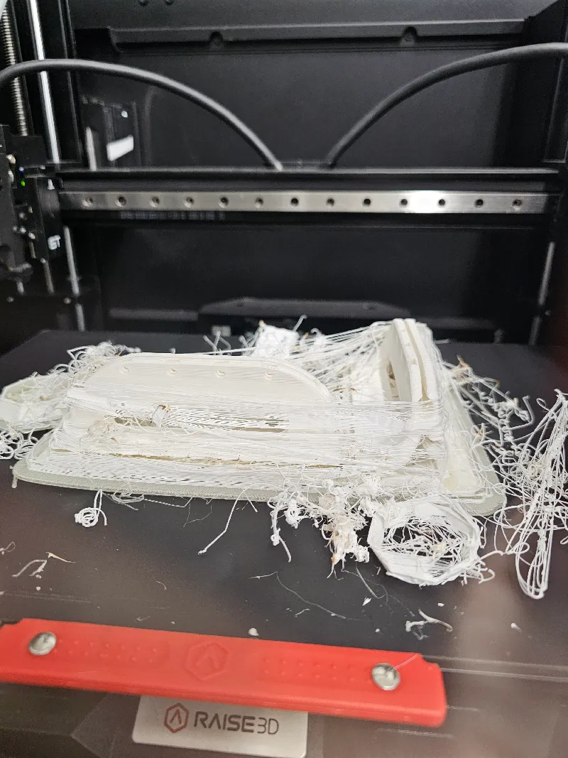
oops
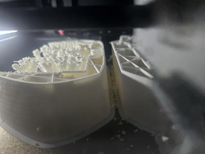
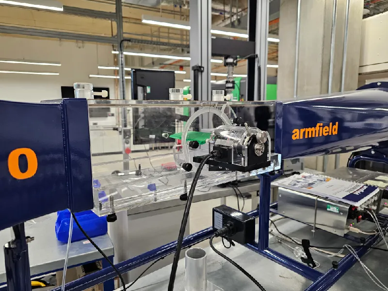 Wind tunnel testing of the wings
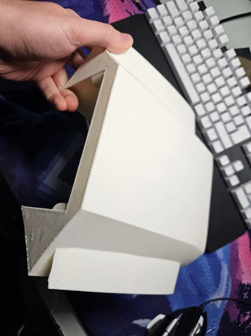
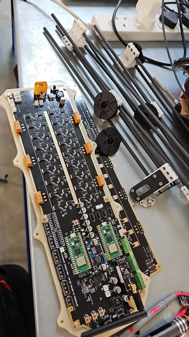
We used 500mm CF rods, which we later joined with 4mm aluminium rods and epoxy to make 1m long CF rods. Its easier if you buy 1m rods from the start.
Due to Nexprint not currently having a file folder system, I have attached the files from Printables. These are organised in folders based on file types. Additionally, There is a Zip file for the Gerber file and Bill Of Materials for the PCB if you want to use that.
Originality of the Model
The author declares that this work is their personally original model
This model is licensed under the following terms:
Credit must be given to the creator
Models(21)
 bl-wing.stlDesigner
1.76 MB

2025-08-09
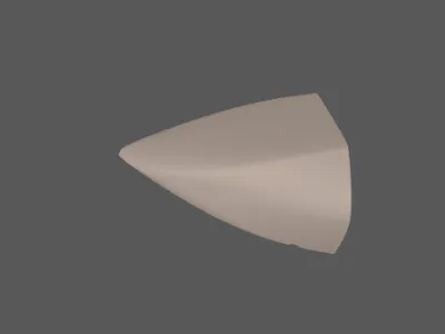 body-1.stlDesigner
1.27 MB
2025-08-09
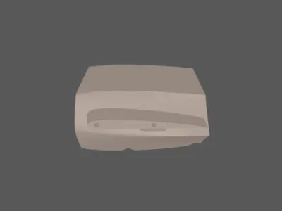 body-2.stlDesigner
1.05 MB
2025-08-09
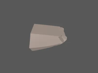 body-3.stlDesigner
335.73 KB
2025-08-09
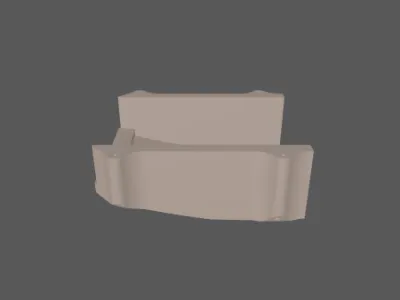 body-4.stlDesigner
441.88 KB
2025-08-09
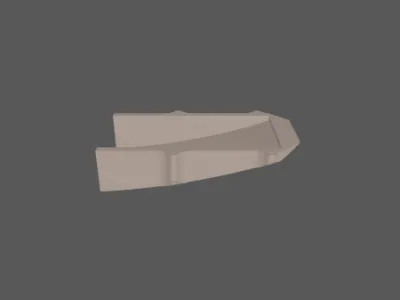 body-5.stlDesigner
324.50 KB
2025-08-09
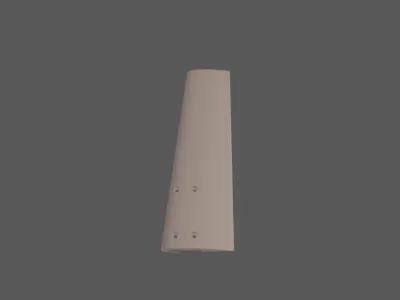 br-wing.stlDesigner
1.76 MB
2025-08-09
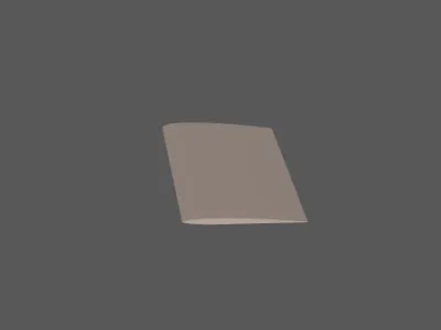 left-wing-1.stlDesigner
1.72 MB
2025-08-09
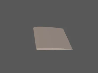 left-wing-2.stlDesigner
1.85 MB
2025-08-09
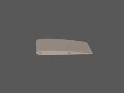 left-wing-3.stlDesigner
845.69 KB
2025-08-09
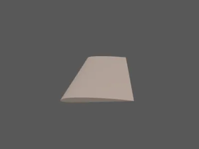 right-wing-1.stlDesigner
1.72 MB
2025-08-09
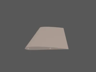 right-wing-2.stlDesigner
1.85 MB
2025-08-09
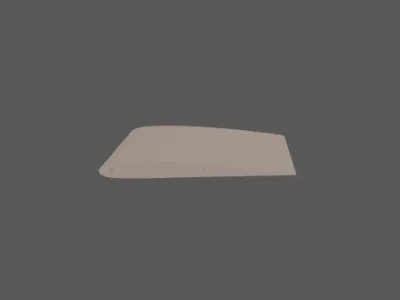 right-wing-3.stlDesigner
842.07 KB
2025-08-09
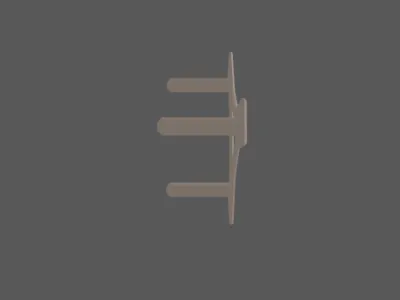 cf-rod-end-cap.stlDesigner
120.79 KB
2025-08-09
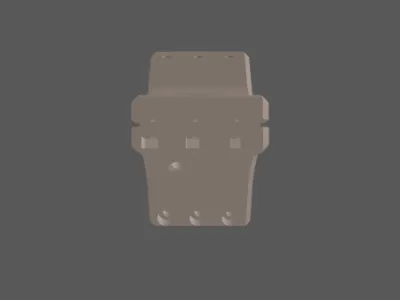 cf-rod-modular-connectors.stlDesigner
957.11 KB
2025-08-09
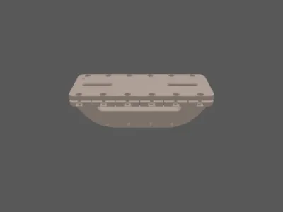 cf-rod-wing-mount.stlDesigner
1.19 MB
2025-08-09
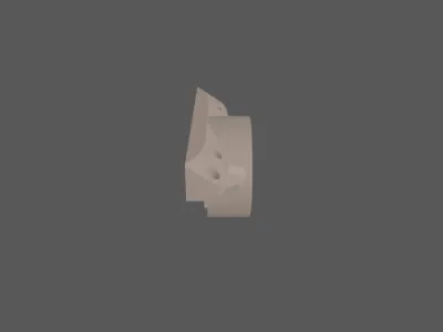 horizontal-motor-mount.stlDesigner
365.41 KB
2025-08-09
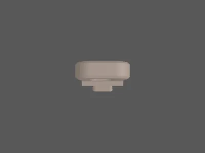 rear-wing-mount.stlDesigner
135.14 KB
2025-08-09
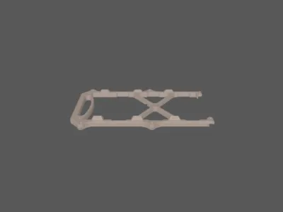 frame-1.stlDesigner
427.43 KB
2025-08-09
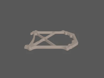 frame-2.stlDesigner
509.55 KB
2025-08-09
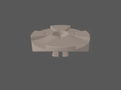 vertical-motor-mount.stlDesigner
966.68 KB
2025-08-09
View all(21)
Attachments(2)
zip
BOM_Gerber_etc.zip
24.59 MB
2025-08-09
zip
Organised_For_3DPrinting.zip
30.68 MB
2025-08-09


