


experiment
science
diy
physics
education
learning
friction
force
motion
school project
diy engineers
inclined plane


18

3
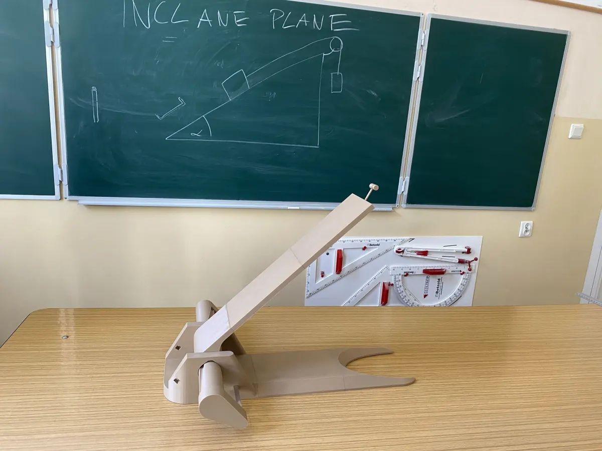
Large Adjustable Inclined Plane – Physics Laboratory Edition
From a Classroom Model to a Real Experimental Platform
This project started as a small educational inclined plane designed for physics demonstrations. After successful classroom testing, I decided to create a much larger and more capable version that allows for longer experiments, greater precision, and significantly more flexibility.
With a 60 cm long track, a 0–90° adjustment range, and a unique screw-driven angle control system, this model is designed for real experiments rather than simple demonstrations.
Whether you’re a student, teacher, physics enthusiast, or maker, this project provides a versatile platform for exploring mechanics in a hands-on way.
Key Features
Large Experimental Surface
The track measures approximately:
600 mm length
120 mm width
The increased size allows objects to travel for a longer time and distance, making measurements easier and more accurate compared to smaller classroom models.
Unique Screw-Driven Angle Adjustment
Unlike most inclined planes that rely on hinges, pins, or fixed-angle supports, this design uses a custom screw-driven lifting mechanism.
The angle can be adjusted continuously from:
0°
up to 90°
The relationship between screw travel and angle is approximately:
1 cm screw movement ≈ 3.75° angle change
This allows the user to calculate and reproduce angles with remarkable consistency using nothing more than a ruler.
Repeatable Measurements
The system was designed with repeatability in mind.
To set a desired angle:
Measure the screw displacement from its starting position.
Move the screw to the required position.
Repeat the same measurement whenever the setup is needed again.
No dedicated angle scale is required.
Typical practical accuracy is around:
±1 mm measurement precision
roughly ±2° angle deviation even under load
The limiting factor is usually the measuring tool rather than the mechanism itself.
Rotating Experimental Surface
One of the most useful features is the ability to rotate the entire inclined plane by 180°.
This allows users to prepare two different surfaces and switch between them within seconds.
For example:
Side A: standard printed surface
Side B: Velcro
Sandpaper
Rubber
Fabric
Foam
Any custom material
This makes friction experiments significantly easier and eliminates the need to rebuild the setup between tests.
Designed for Real Physics Experiments
This model can be used for a wide variety of educational experiments, including:
Friction
Static friction
Kinetic friction
Coefficient of friction determination
Comparison of different materials
Motion on an Inclined Plane
Acceleration measurements
Distance-time relationships
Velocity calculations
Newtonian mechanics
Energy
Potential energy
Kinetic energy
Energy conversion
Pulley and Counterweight Systems
The top section includes a mounting point for:
strings
pulleys
hanging masses
allowing experiments involving connected bodies and force balance.
Printable Experimental Sled
Included files also contain a printable sled/container.
The sled features side walls and can be loaded with:
weights
metal parts
sand
coins
other test masses
This makes it easy to investigate how mass affects motion and friction.
Strength and Stability
The mechanism has been physically tested with:
approximately 500 g load placed at the far end of the track
The system remained stable and capable of lifting the inclined plane without structural failure.
For the smoothest operation, it is recommended to:
set the angle before applying heavy loads
Once adjusted, the mechanism reliably maintains its position without slipping.
Required Non-Printed Parts
The project requires only a few additional components.
Square Rod
Approximately 1 meter of:
10 × 10 mm square rod
Recommended materials:
aluminum
steel
rigid plastic
Used for:
guide rail support
screw reinforcement
structural connections
Optional Surface Board
Recommended dimensions:
21 mm × 10 mm cross-section
Used as the inclined plane surface.
However, this part can be fully replaced with printed components if desired.
Printing Information
Supports
✅ No supports required
Material
Compatible with:
PLA
PETG
ABS
ASA
most common printing materials
Layer Height
Any standard layer height works well.
Estimated Print Time
Approximately:
24 hours
Filament Usage
Approximately:
800 g
depending on slicer settings.
Maintenance
The mechanism works without lubrication.
However, for best performance and reduced adjustment force, it is strongly recommended to lightly lubricate the entire screw thread using:
grease
machine oil
PTFE lubricant
This significantly improves smoothness during adjustment.
Educational Applications
Suitable for:
High school physics
Technical schools
University introductory mechanics courses
STEM workshops
Home laboratories
The model was originally developed and tested as a school physics project and proved highly effective as a practical teaching aid.
Why This Design?
Most inclined planes available online are either:
fixed-angle
very small
difficult to reproduce accurately
This design focuses on:
large scale
continuous adjustment
repeatability
modularity
ease of printing
The screw-driven mechanism provides a level of control rarely seen in 3D printable educational equipment.
Final Notes
This project was created to demonstrate that 3D printing can produce not only display models, but also serious educational tools.
If you print one, experiment with it, improve it, or adapt it for your own classroom, I would love to see the results.
Happy experimenting! 🔬⚙️📐
Bill of materials
- NameQuantityNotes
- 110x10mm aluminium profile or other with the same dimantions ~~80cm1
Originality of the Model
The author declares that this work is their personally original model
This model is licensed under the following terms:
Credit must be given to the creator
Models(15)
 Part Studio 6 - surface connector.stlDesigner
0.67 KB

2026-05-30
 Part Studio 7 - smaller conector.stlDesigner
0.67 KB
2026-05-30
 Part Studio 7 - bigger conector.stlDesigner
0.67 KB
2026-05-30
 Part Studio 9 - container.stlDesigner
26.45 KB
2026-05-30
 Part Studio 8 - Cart.stlDesigner
12.19 KB
2026-05-30
 Part Studio 6 - Body 1.stlDesigner
25.86 KB
2026-05-30
 Part Studio 6 - Body 2.stlDesigner
4.18 KB
2026-05-30
 Part Studio 6 - Body 3.stlDesigner
47.25 KB
2026-05-30
 Part Studio 6 - Cover plate.stlDesigner
24.01 KB
2026-05-30
 Part Studio 6 - Puly holder.stlDesigner
187.09 KB
2026-05-30
 Part Studio 6 - Screw extantion.stlDesigner
213.46 KB
2026-05-30
 Part Studio 6 - Screw main body.stlDesigner
216.10 KB
2026-05-30
 Part Studio 6 - Surface 1.stlDesigner
51.45 KB
2026-05-30
 Part Studio 6 - Surface 2.stlDesigner
2.62 KB
2026-05-30
 Part Studio 6 - Surface 3.stlDesigner
5.84 KB
2026-05-30
View all(15)