





EMG
Arduino
Muscle
Controller
Control
Brain
EMG signal
BioSignal
Biomedical Engineer

 Standard profile
2-disc
PLA
Designer

91

6
Description
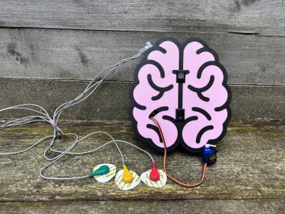
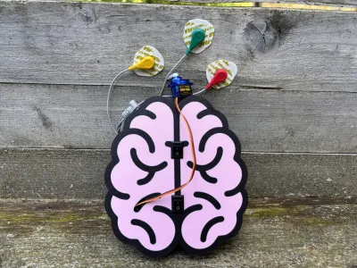
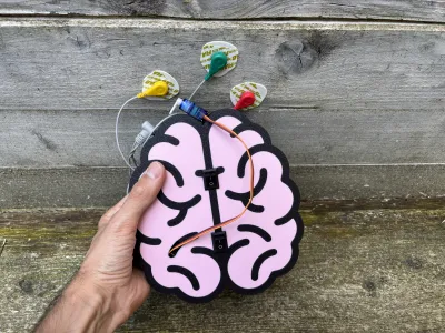
Welcome of one of the project we're most enthuiastic for: THE EMG MUSCLE MOCNTROL!
Electromyography (EMG) is a technique that measures the electrical signals produced by your muscles when they contract. Every time you move — or even just try to move — a muscle, it generates a small electrical pulse. EMG sensors can capture these signals directly from the surface of your skin. With the right setup, these signals can be processed and used as control inputs for electronic devices.
In this project, we want to use EMG signals to control a servo motor with the help of Arduino. While EMG has been used in many research and medical applications, it’s still not very common to see it directly driving small robotic parts in DIY projects. Our goal was to change that.
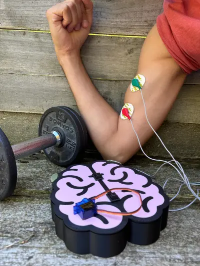
We built a system where your muscle activity (for example, flexing your forearm) can rotate a servo motor to a new position, or return it back to rest when you relax. This could open the door to hands-free interfaces, biofeedback experiments, or simply a fun and interactive way to learn about human-machine
🔧 How it works:
Place the EMG electrodes on your arm (or another muscle you want to use).
The EMG sensor detects the muscle activity and outputs a signal proportional to the contraction.
The Arduino reads this signal, filters it, and decides whether to move the servo.
The servo motor responds instantly — rotating clockwise or counterclockwise depending on your setup.
🎯 Applications:
Try it as an introduction to biofeedback systems.
Build interactive projects where muscles directly control moving parts.
Learn the basics of human-machine interaction in a hands-on and engaging way.
👉 A full assembly video is available to guide you step by step.
And for those who prefer written instructions, you’ll also find a detailed build and programming guide attached below. 🛠️🎥👇
ASSEMBLING INSTRUCTIONS:
STEP 1
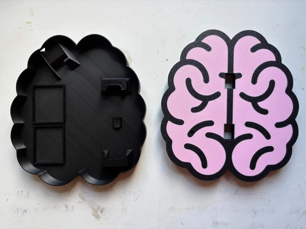
3D printing

STEP 2
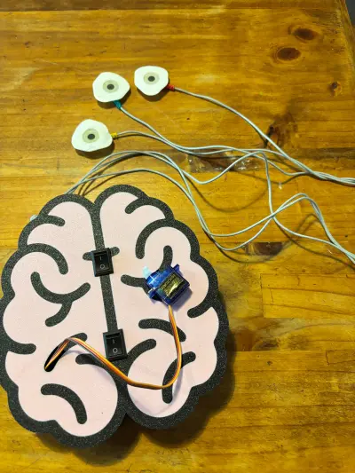
Prepare the switch and solder in series to the 9V connector, following the schematic.


STEP 3
Open all the channels of the cable-connector and place a piece of double-sided tape to ensure it in its place.


STEP 4
Do the same thing with mini breadboard.


STEP 5
Ensure the electrical switches to the control up-cover.

STEP 6
Connect the 9V batteries usign the 9V connectors. Be carefull not to shortcircuit the red and black wire of the same battery.

STEP 7
Connect the wire following the video below or using the schematic that you can found in this guide.
STEP 8
Download the provided Arduino sketch (.ino file) from the link (here). This file contains the logic required to control the circuit and servo motor.
STEP 9
Open the Arduino IDE on your computer.
1. Load the .ino file you downloaded.
2. Select the correct Board (e.g., Arduino Uno) and Port from the Tools menu.
3. Connect your Arduino board to the computer using a USB cable.
4. Press the Upload button in the IDE.
5. Wait until the message “Done uploading” appears, confirming that the program has been successfully transferred.
STEP 10
Verify that all wires are securely connected.
Ensure that no exposed wires are touching each other.
Power on the circuit by switching on the control switch.
Observe the behavior of the servo and components: the system should respond as expected according to the uploaded Arduino program.
📌 Note: Before uploading the code, make sure you have installed all the required Arduino libraries (for example, Servo.h) using the Arduino IDE Library Manager.
Assembling Video: Video
Bill of materials
- NameQuantityNotes
- 1Read the PDF!1
Originality of the Model
The author declares that this work is their personally original model
This model is licensed under the following terms:
This work is licensed under a Standard Digital File License. Digital files have a strict non-commercial, personal use only license.
You shall not share, sub-license, sell, rent, host, transfer, or distribute in any way the digital file or 3D printed versions of this object, nor any other derivative work of this object in its digital or physical format (including remixes of this object). You can not host these files on other digital platforms, web stores or cloud repositories. The objects may not be used in any way whatsoever in which you charge money, collect fees.
Models(1)
- MUSCLE+CONTROL.3mfDesigner

630.46 KB

2025-09-03
Attachments(1)
pdf
Muscle+Control+2.pdf
4.49 MB
2025-09-03


