


Piggy Bank
Safe
Bank

- 0.2 mm layer height, 2‑wall walls, 15% infill density

7-disc
PETG/PLA
Designer

5

0
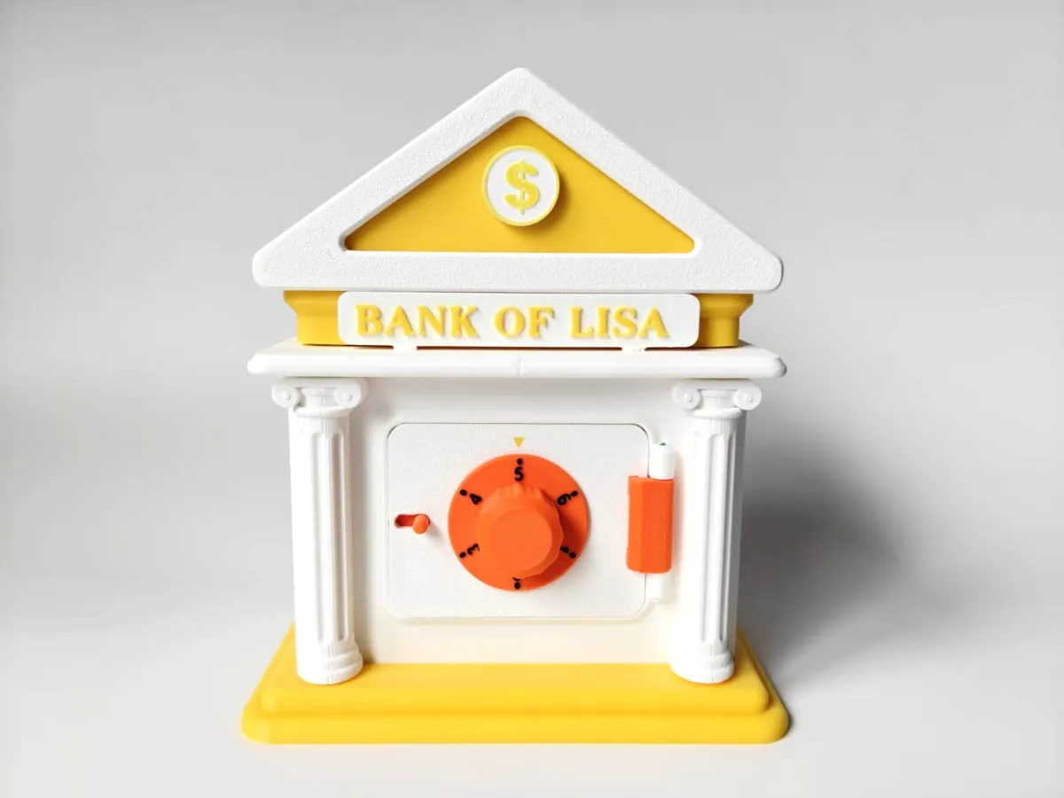
A bank-shaped piggy bank featuring a simulated safe‑type combination lock.
It allows you to deposit and withdraw money by unlocking the combination, though like a real safe, it can also be forcibly opened.
The combination is customizable.
The signage is customizable.
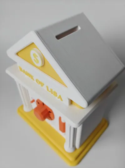
Assembled dimensions are approximately 135 × 90 × 155 mm.
Please customize the signage by modifying the text and font in your slicing software.


Combination Lock Mechanism and Custom Passwords
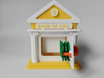
The mechanism consists of three dials—A, B, and C. Dial A is directly connected to the outer handle wheel, while B and C are not directly linked; instead, they rotate via “drive pins” located on dials A, B, and C.
Dial A directly drives dial B, which has double-sided drive pins. Through dial B, dial A indirectly drives dial C.
Each dial features a “notch/gate.” When all three notches align with the bolt position, the bolt can be pushed open, allowing the door to unlock.
How to Determine the Combination:
During assembly, the “drive pins” can be inserted into any one of five holes on each dial. Note that pin B must protrude on both sides, while pins A and C should protrude toward dial B.
In any case, rotate counterclockwise (viewed from the front of the piggy bank, i.e., turning left) one full rotation, then continue rotating until dial C’s notch aligns with the bolt. At this point, check the dial positions—the first combination is shown below as “2.”

Next, rotate clockwise for one full rotation, then continue rotating until dial B’s notch lines up with the bolt. As shown below, this corresponds to “1.5.”

Finally, rotate counterclockwise until dial A’s notch faces the bolt. This completes the third combination. At this point, the bolt can slide rightward through the three aligned notches, unlocking the door.

Please ensure you clearly know and record the combination before locking the door...
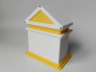
Assembly instructions are as follows:
The position of the drive pins can be adjusted freely, as long as their orientation is correct.


The snap‑fit components can be challenging to assemble; tweezers may be helpful. If the fit is tight enough, no additional tools are needed, or glue can be used instead. The four pins on the base are slightly shorter.
The four pins in the center of the diagram are longer.


You’ll need two lengths of filament to serve as axles.


Originality of the Model
The author declares that this work is their personally original model
This model is licensed under the following terms:
Credit must be given to the creator
Remixes must be shared under the same license
Models(1)
- Bank CC2 .3mfDesigner

685.26 KB

2026-05-26