




framework
pc
case
mini
minipc
enclosure
housing
framework13
mainboard
main
board


162

7
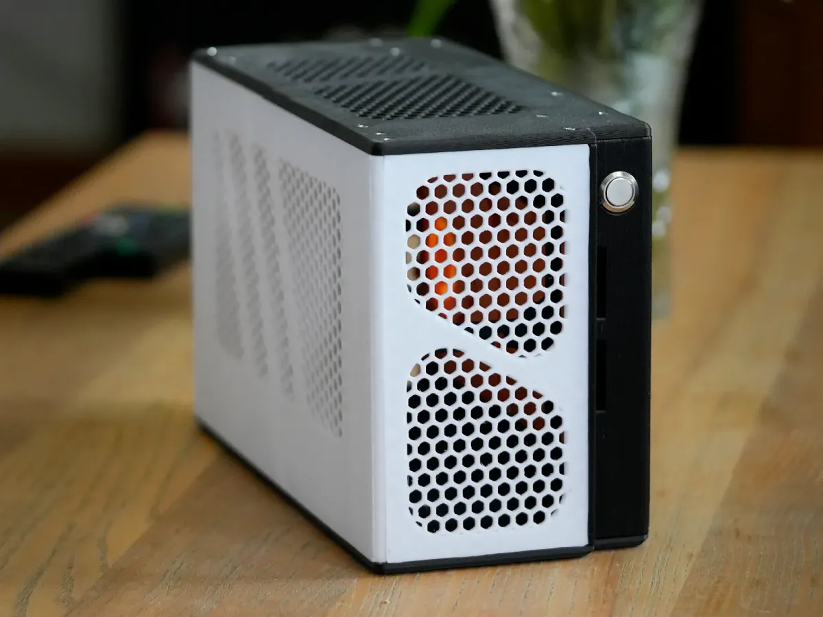
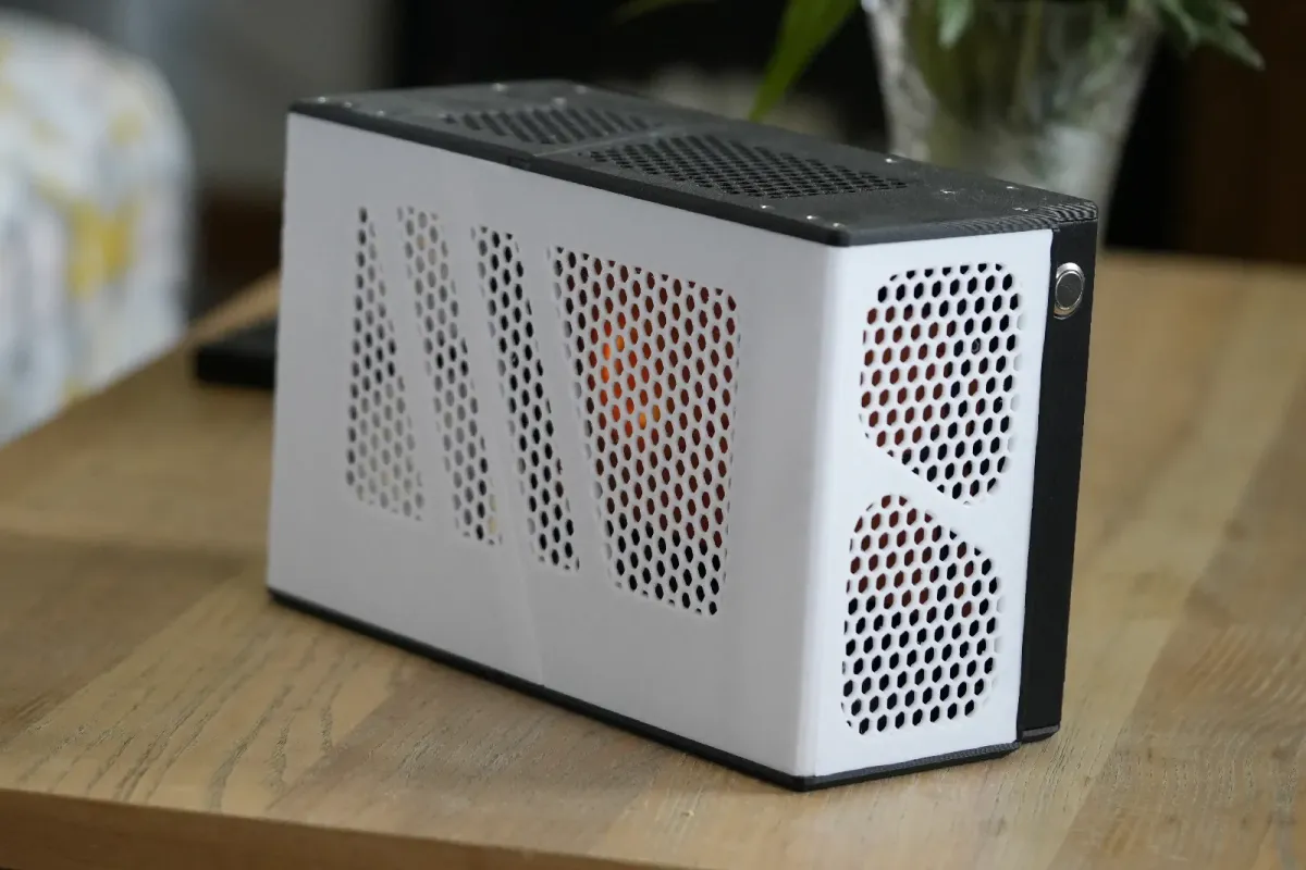
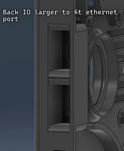
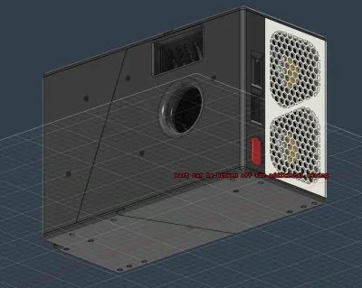
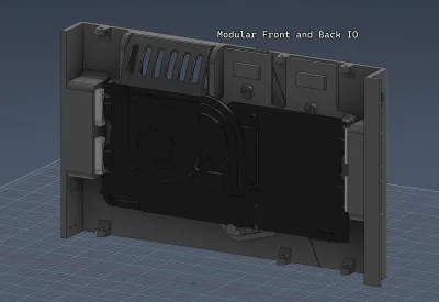
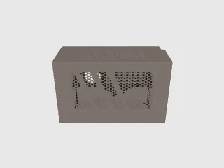
A mini pc case with modular front and back IO. For framework 13 mainboard!
Hardware:
- M3 Nuts x38
- M3*16 screw x10
- M3*8 screw x26
- M3*6 screw x2
- Self-tapping PC Fan screws x16
- 80mm PC fans (largest depth at 30mm) x4
- PWM Fan controller (check the pins match your fans) x1
- [A way to power the fan controller] x1 (this may be easier or harder depending on what fan controller you use)
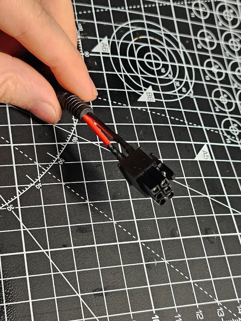
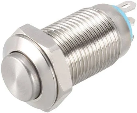
- 12mm Power button (hole sizes at 12.9mm, 9.9mm, 11.9mm) x1
(check that your button is momentary, not latching)
- Dust mesh (optional)
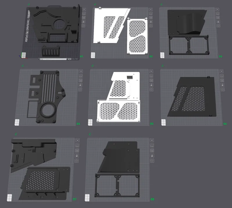
Approx material cost: 30USD, at around 1.2 kg of PETG (If possible, please print with ABS due to heat warping over time. PLA is not recommended)
Pre-print Notes:
After printing one part, i suggest making that part not printable. This avoids you printing the same part twice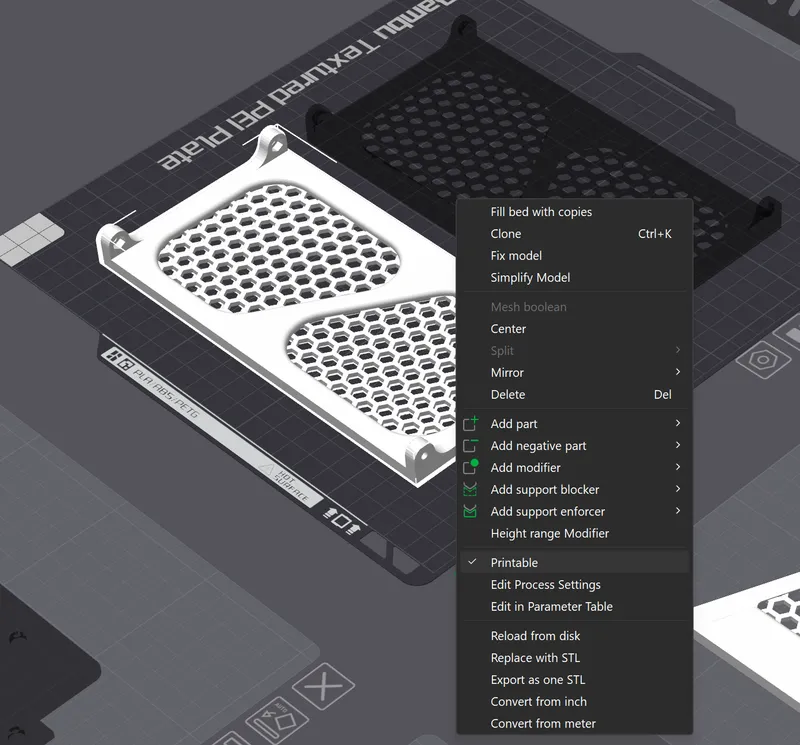
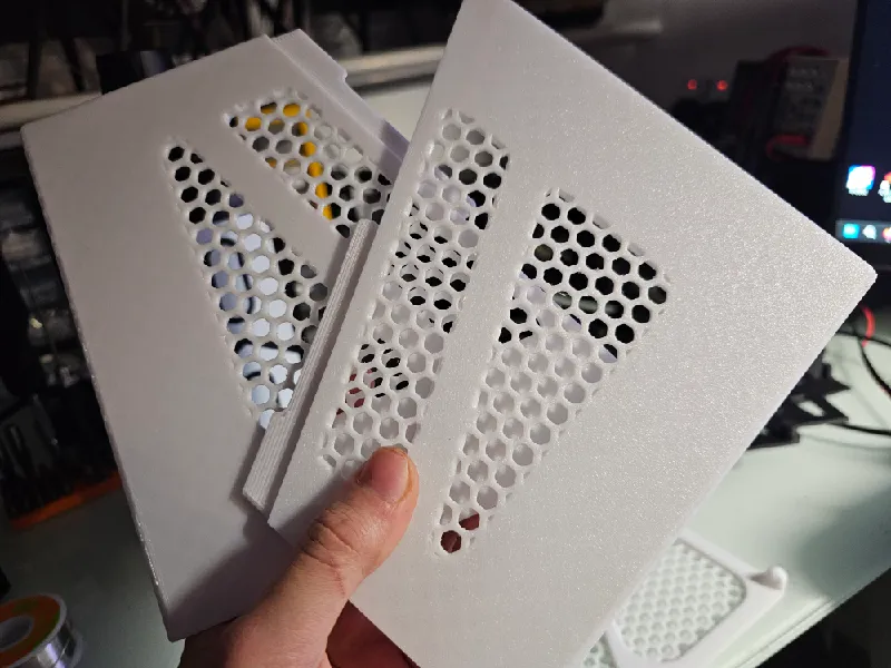
Assembly instructions:
1: Check the diameter of your button, pick a fitting diameter of BackS1. If your size isn't available, modify the step file, or use a step drill bit. Print all parts.
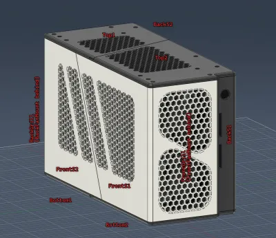
2: Some parts are split in two. Apply a small amount of CA glue on the contacting edges, and join the parts together
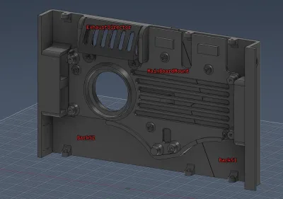
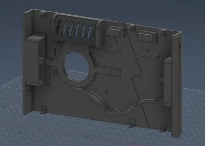
[Bottom1 & Bottom2], [Top1 & Top2], [FrontS1 & FrontS2], [BackS1 & BackS2]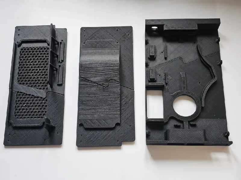
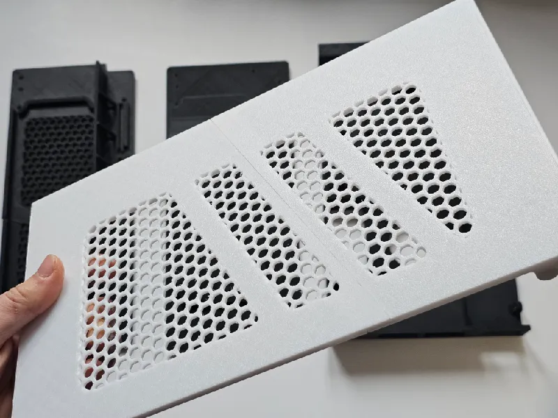
(forgive the atrocious print quality of the black parts😭)
3: I designed the M3 nuts to be heat-set, however, they can just be pushed in with a mallet, clamp, or other means. Insert all into hexagonal recesses.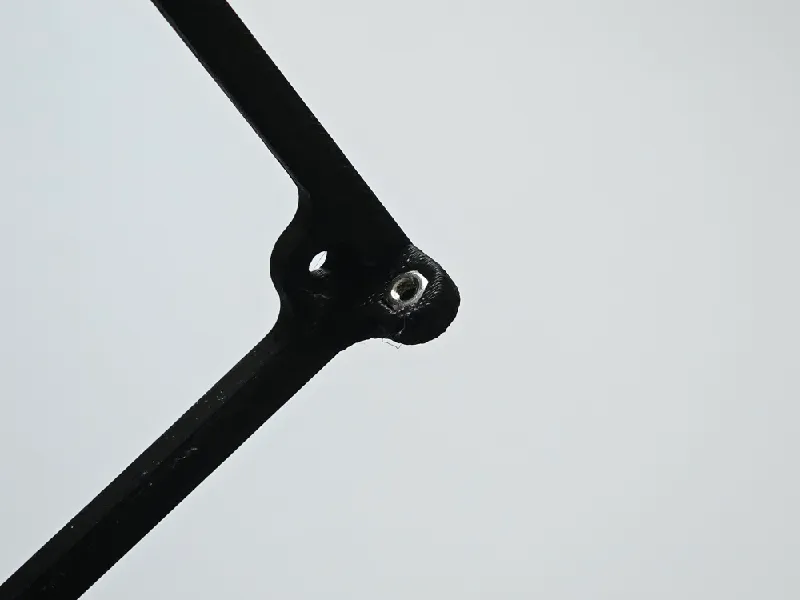
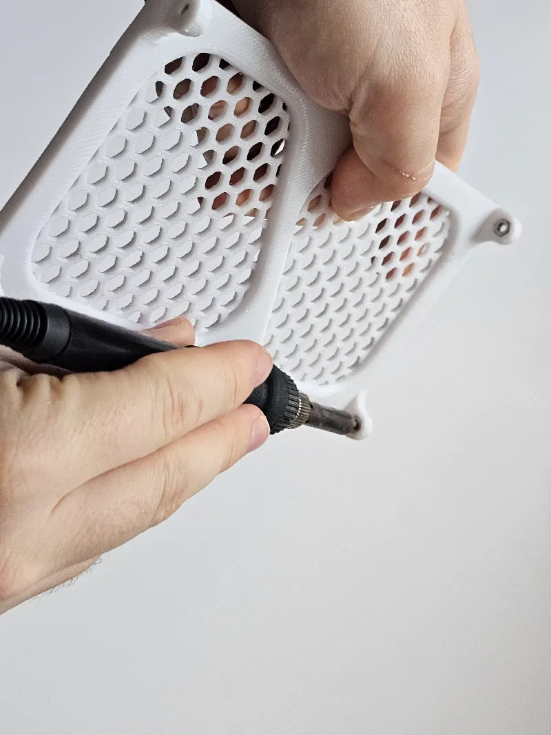
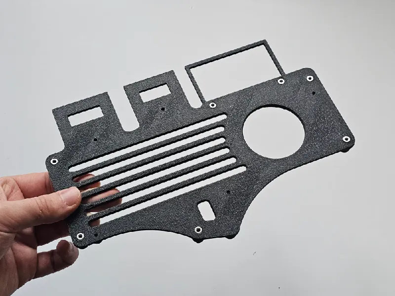
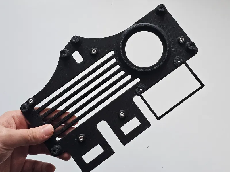
4: screw on the ExhaustDirector to the mount using two M3*6 screws. Make sure that the screws dont poke out of the nut on the other side.
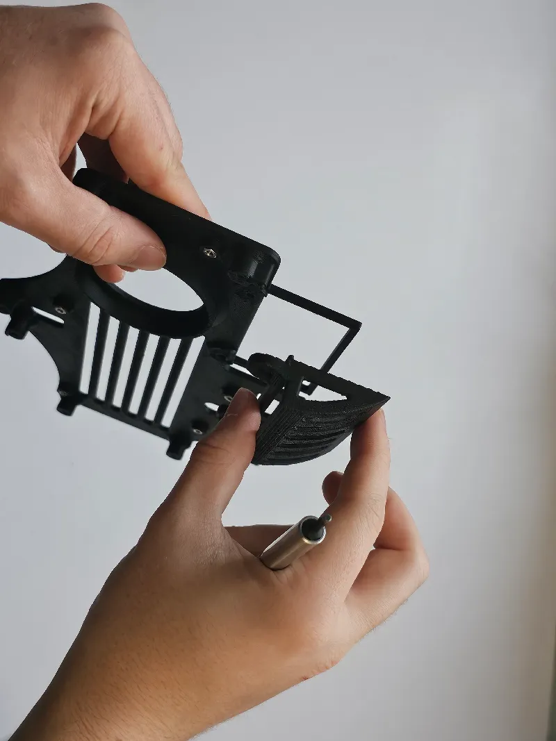
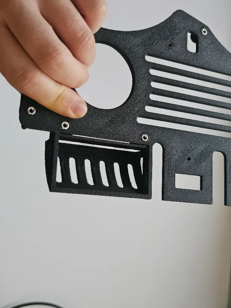
5: Attach the mainboard to the MainBoardMount using five M3*16 screws.
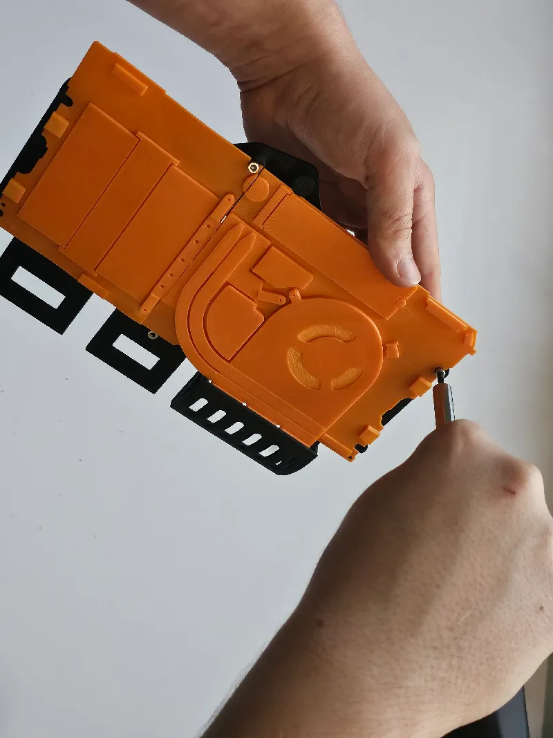
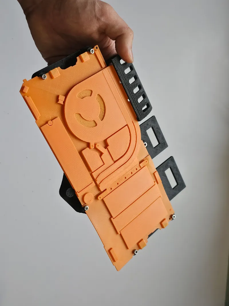
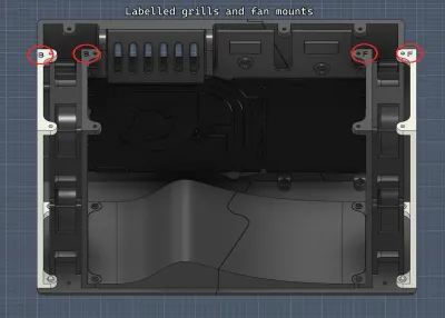
6: Set aside and attach 4x 80mm fans to both the front and back FanMounts. Double check orientation. *All four fans aren't necessary for function.
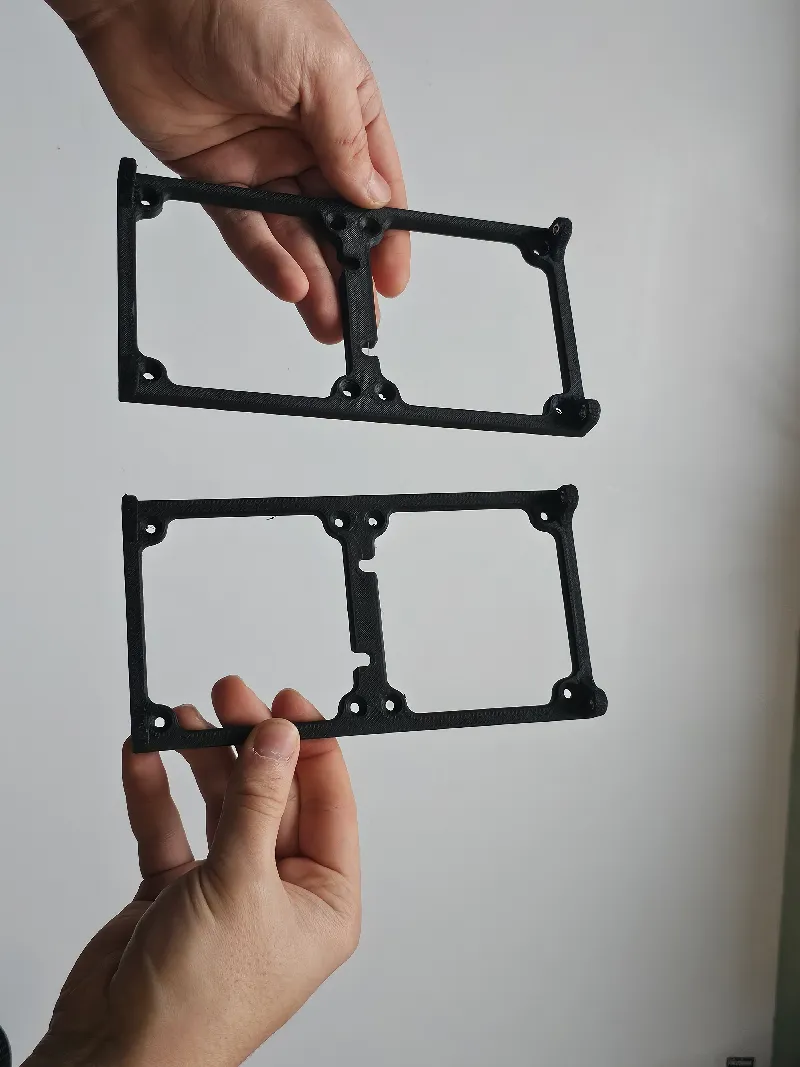 (i do not have 80mm fans unfortunately)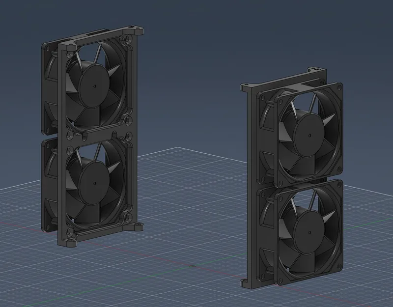
7: Connect each fan to a fan controller. Depending on your chosen controller, it can either connect to the board itself, or may need external power.
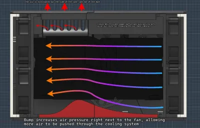
Since the board has its own fan, these external fans do not need to interface with the mainboard at all. Keeping them at a quiet 30-40% speed is sufficient.
8: Insert the power button through the BackSide. If it doesnt fit, use a stepped drill bit to adjust the size until your button fits. Connect the button to the mainboard. (i don't think soldering to the board is required to make this connection)
9: Proceed by screwing the mainboard mount to the BackSide assembly. This required five M3*16 screws
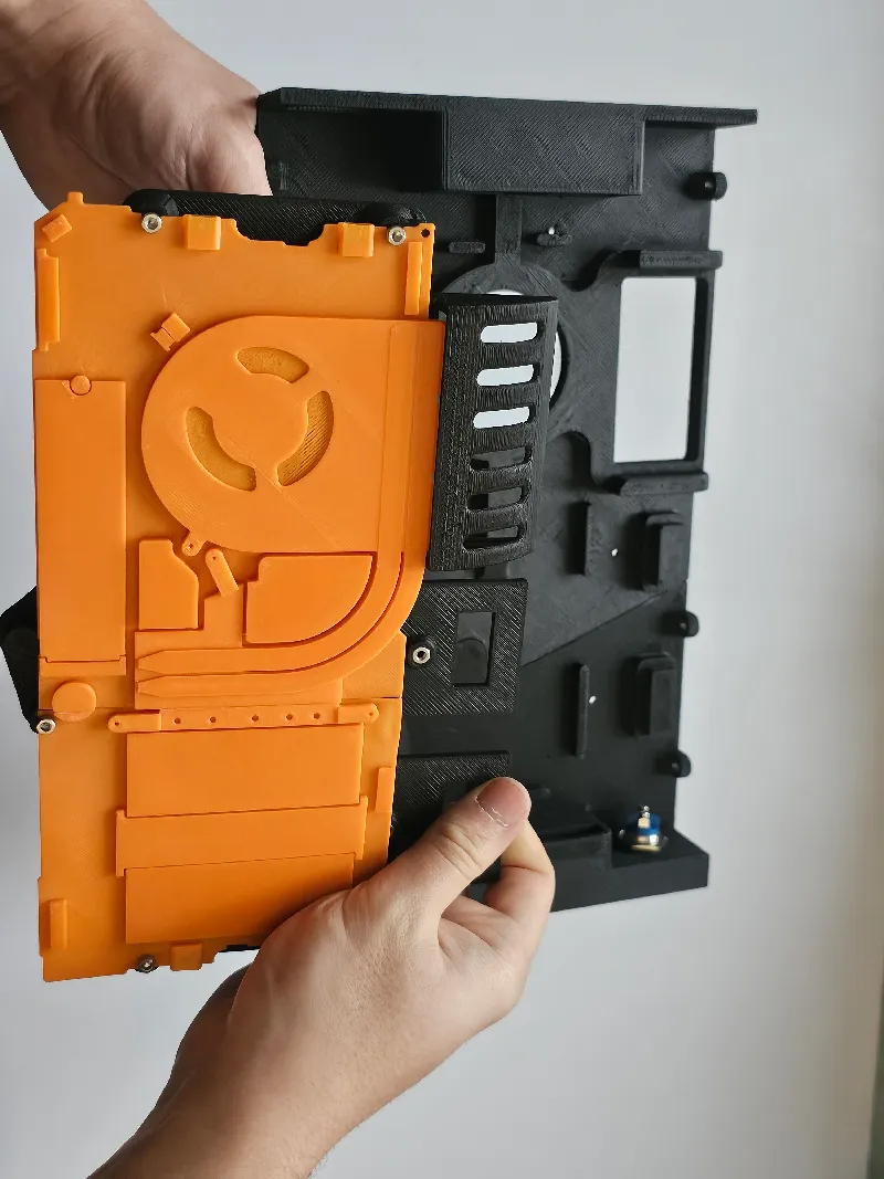
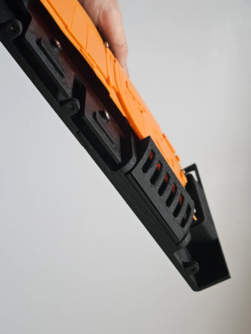
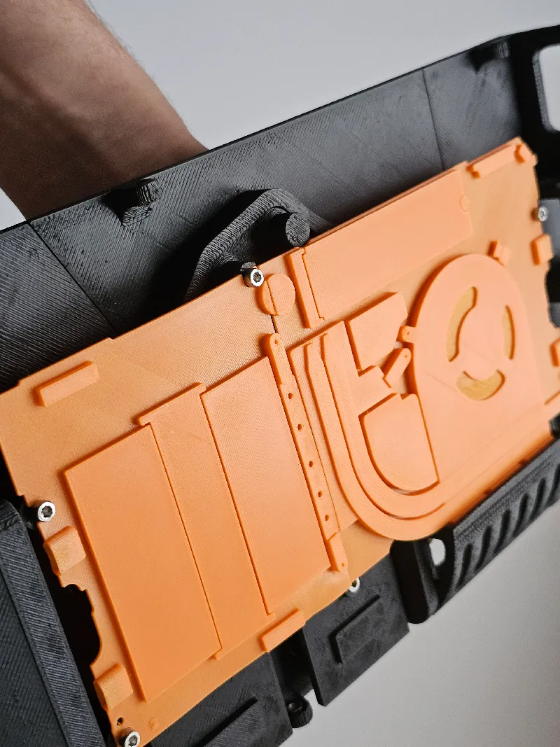
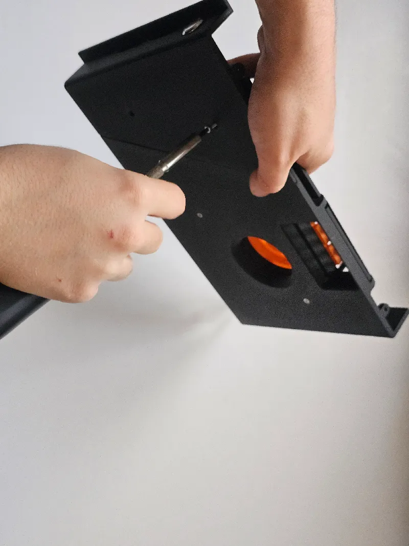
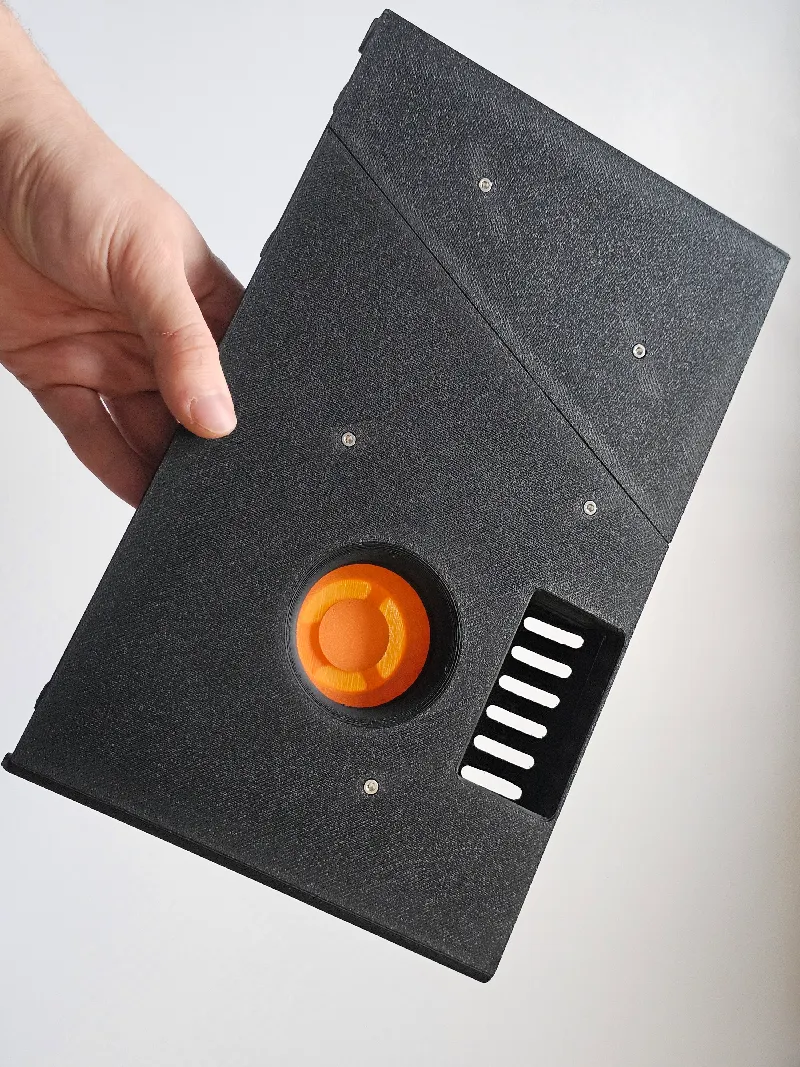
10: Assemble all of the parts in this order:
Top ← BackSide (three M3*6 screws)
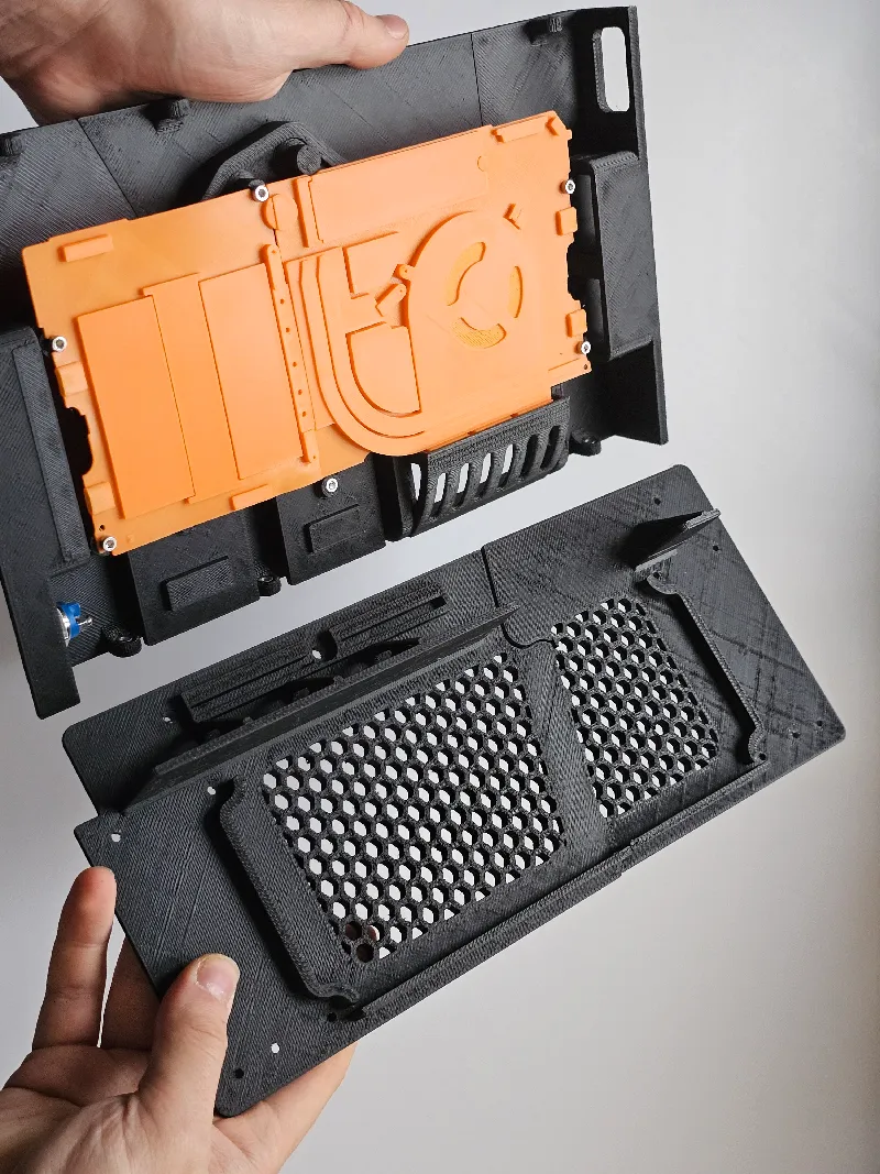
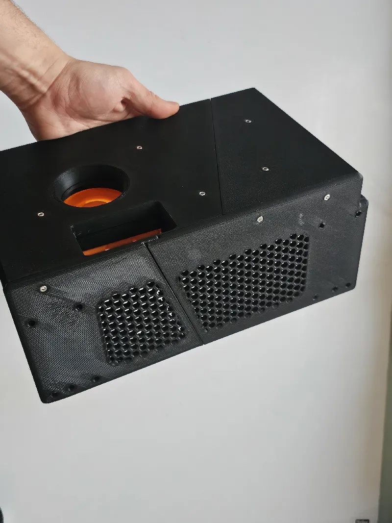
Top ← Fan Mounts x2 (two M3*6 screws per mount)
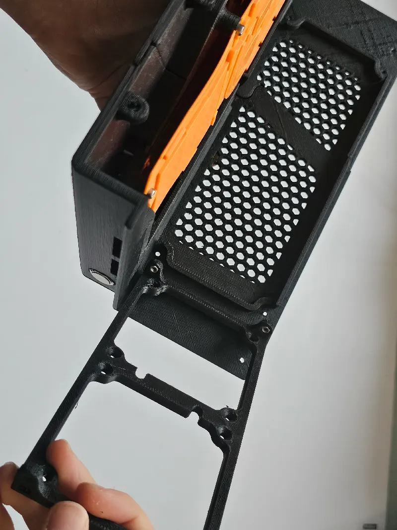
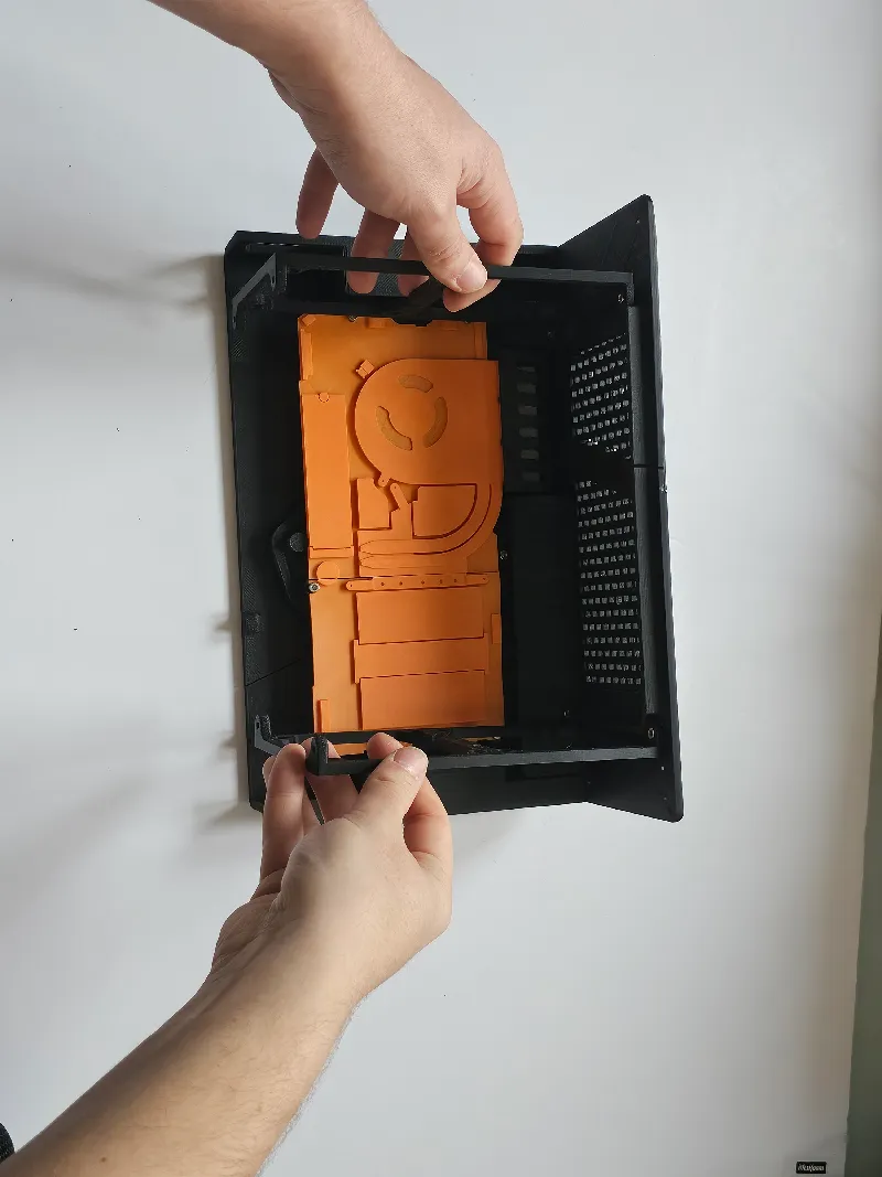
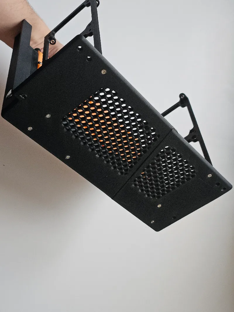
Top ← Fan grills x2 (two M3*6 screws per grill).
Consider cutting a dust mesh into a rectangle and gluing it on the inside of each fan grill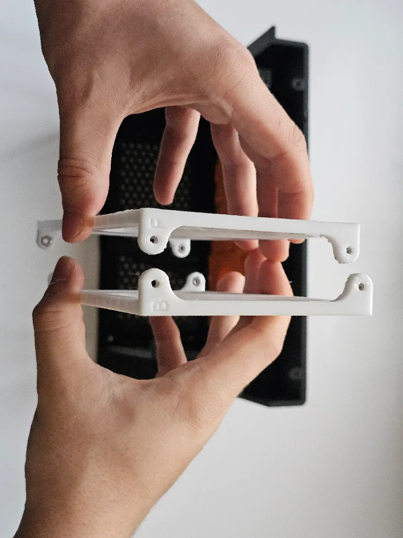
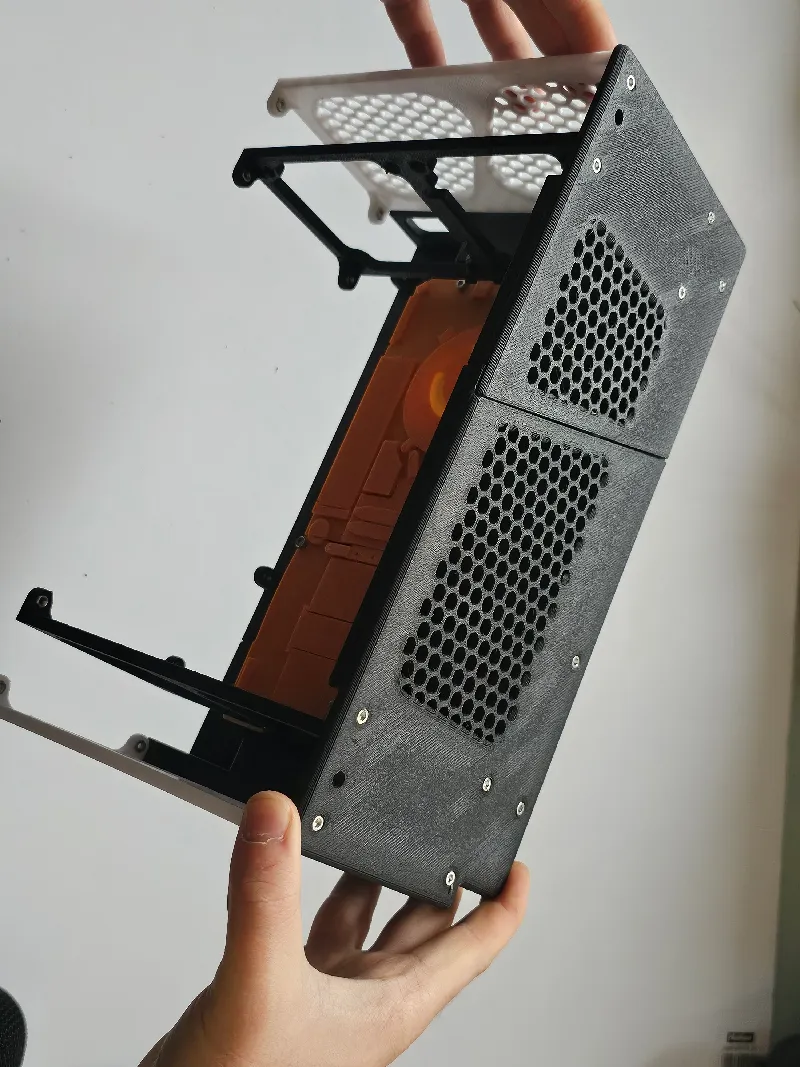
*meanwhile, you can cable manage to hide the wires if you wish. The wires would be hard to see regardless, so they don't have to be neat
Current assembly ← Bottom (11 M3*6 screws)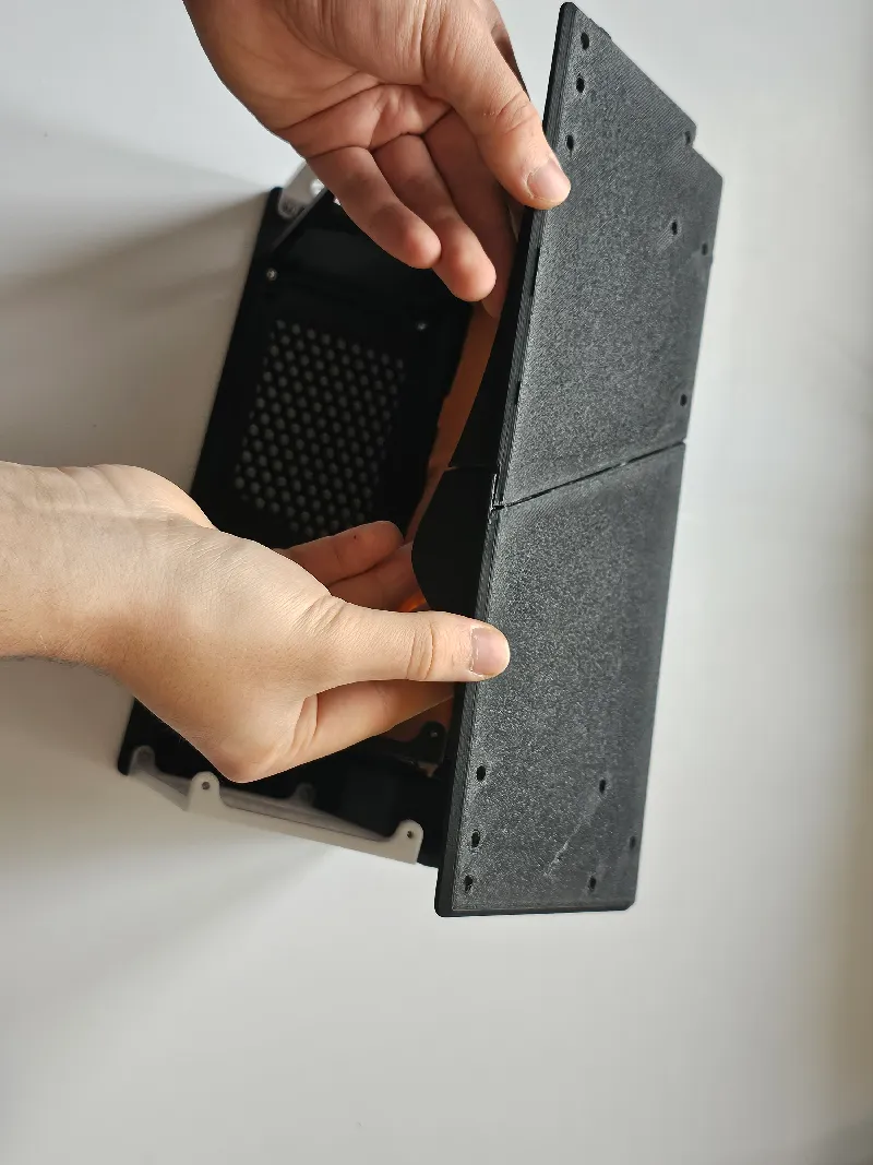
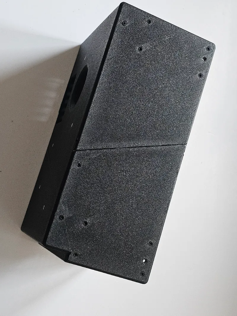
(I used black screws for this as i ran out of silver M3*6s)
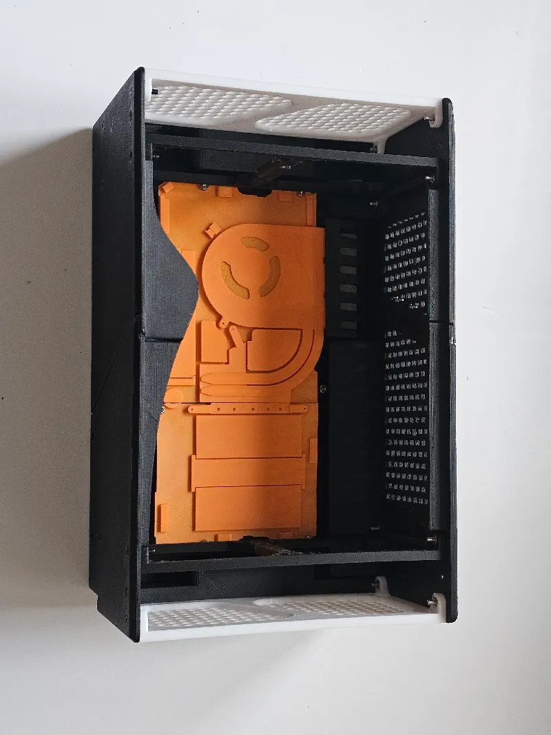
Finally, double check all wiring and check if the extension cards fit.
This is also the moment where you can take advantage of the internal space. Whether adding a power supply, taping in a 2.5" ssd, or adding RGB lights.Current assembly ← FrontSide (four M3*6 screws)
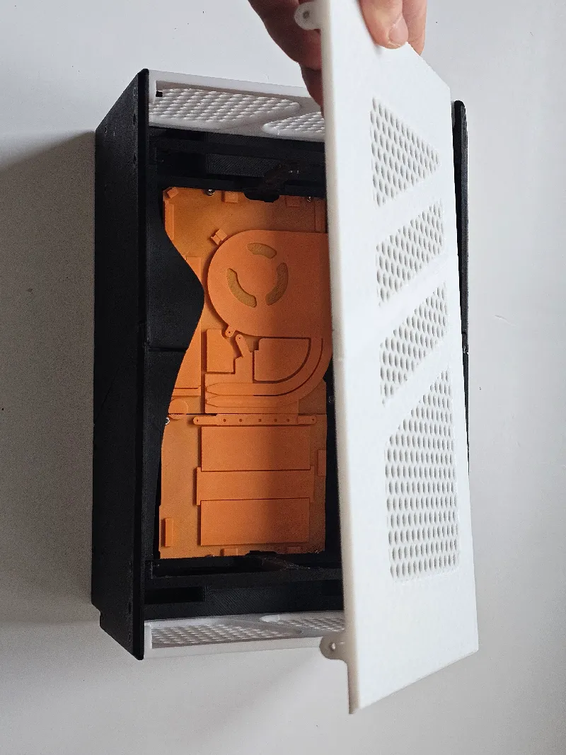
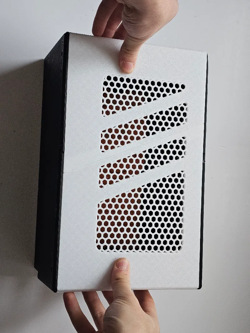
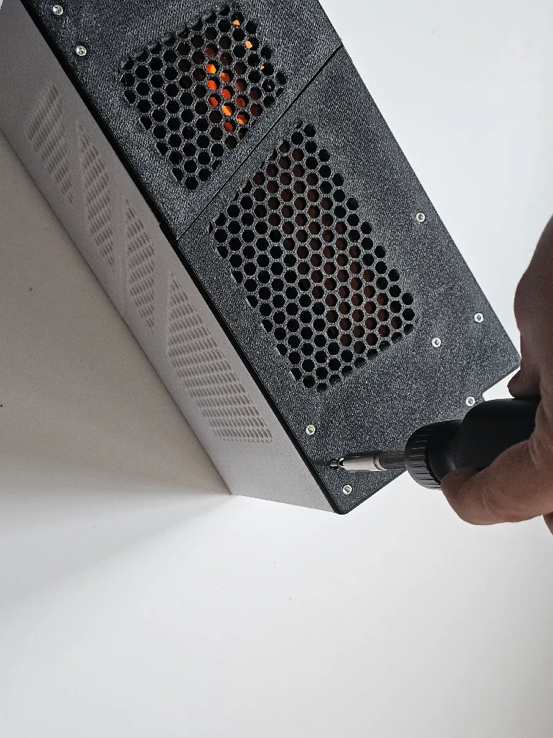
Since the power button is on the side of the case, consider some silicone anti-slip pads
Version 2 Plan:

Rework expansion slots to have a more satisfying insertion, while keeping the card more secure. This could be done with two flexible pins on each side of the lot - I cannot implement this now as i do not own expansion cards to test this on

Rework the split parts so that they snap together, rather than needing to be glued

Add additional mounts for more internal components such as wifi card, speakers, and more

Mounts for a 3.5 inch Hard drive


Set up dedicated cable routing channels, as well as hooks to keep the cables managed within the case

The nuts aren't needed per se. I can make the bolts self-threading.

The exhaust director does not need to be a seperate part. They should be fused together

Rather than gluing the dust mesh to the fan grills, ill have holders to make the attachment process easier (and the mesh can be easily replaced)

[+ More issues to be found]
27/01/2025:
2nd place in tournament! Although i won't be getting a framework board, I'll still work on a V2!
Nexprint comment: For organised files in folders, check out: https://www.printables.com/model/1093504-framework-mini-pc There are also more images too as nexprint only allows 10 preview photos
Bill of materials
- NameQuantityNotes
- 1please reference hardware list at top of description!1
Originality of the Model
The author declares that this work is their personally original model
This model is licensed under the following terms:
Credit must be given to the creator
Models(18)
 bottom2.stlDesigner
144.42 KB

2025-09-01
 framework-pc-case-rev3-step.stepDesigner
15.15 MB
2025-09-01
 backfanmount.stlDesigner
235.04 KB
2025-09-01
 backgrill.stlDesigner
718.54 KB
2025-09-01
 framework-pc-case-rev3.stlDesigner
5.07 MB
2025-09-01
 backs1-99mm.stlDesigner
275.67 KB
2025-09-01
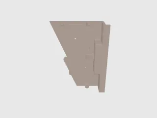 backs1-119mm.stlDesigner
275.67 KB
2025-09-01
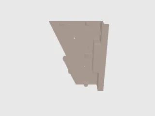 backs1-129mm.stlDesigner
275.57 KB
2025-09-01
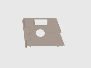 backs2.stlDesigner
405.55 KB
2025-09-01
 exhaustdirector.stlDesigner
1.68 MB
2025-09-01
 mainboardmount.stlDesigner
635.14 KB
2025-09-01
 bottom1.stlDesigner
128.30 KB
2025-09-01
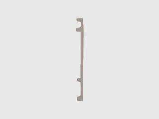 frontfanmount.stlDesigner
214.34 KB
2025-09-01
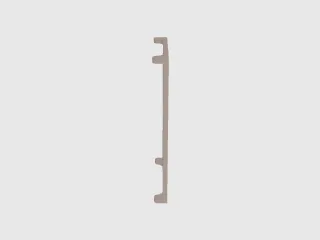 frontgrill.stlDesigner
697.84 KB
2025-09-01
 fronts1.stlDesigner
739.05 KB
2025-09-01
 fronts2.stlDesigner
577.33 KB
2025-09-01
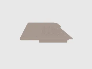 top1.stlDesigner
365.90 KB
2025-09-01
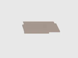 top2.stlDesigner
600.08 KB
2025-09-01
View all(18)


