


2

1
Update 11/30/18 When assembling a new printer for a friend, I found the keepers with the embedded nut had a cavity that was undersized. I replaced them with new models that are easer to embed a nut and require no support.
Update 10/9/17 , 12/3/16 See below.
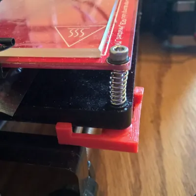
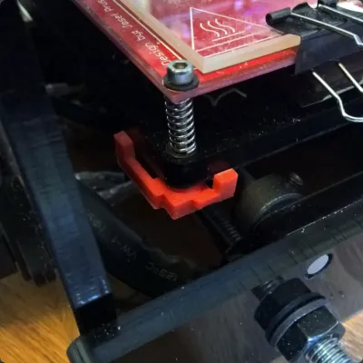
The bed leveling adjustment screws on my Prusa I3 printer use a cap screw, spring and a wingnut. In order to adjust the screw, you have hold one part while turning the other. This part and a 3 mm hex nut replaces the wingnut and allows you to adjust the bed leveling screws using a hex driver on the cap screw without having to hold onto a second part.
There are a couple versions. The one with the long arms is the easiest to print and install. The one with one shortened arm was required to avoid interference with the frame and collars on the smooth rods of the Y axis at the back of the printer. The short arm lies along the X axis, the long arm along the Y axis.
The keeper with the short arm needs a mirror image copy along with the one shown in order to fit on both sides of the print carriage. Repetier and probably others will easily generate a mirror image copy.
The keeper with the short arm requires support, which can be difficult to remove from the hex nut recess. The one with the long arms requires no support.
Why it looks the way it does:
On my Printer, the hole pattern of the carriage does not match the hole pattern of the bed heater, therefore the adjusting screws are at an angle. The cone provides a pivot point to accommodate the misalignment of the screw connecting the two pieces. The arms and the pads that protrude from them press against the print bed carriage and prevent the nut from turning. The thickness push-out of the pad at the end of the arm provides some tension to keep the nut from turning if the hole pattern is such that both arms don't contact the carriage.
UPDATE 10/9/17 NOTE: i HAVEN'T PRINTED THESE, SO IF YOU RUN INTO A PROBLEM, ADD A COMMENT. Add a comment anyway I and others would like to hear about your experience.
I added a version without the cone and containing a cavity for inserting a nut during printing. To insert the nut, you need to stop the printer before it prints the layer that closes the cavity, and insert a 3 mm nut. This requires a patch in the G-code, unless your control software accommodates pauses. I'm familiar with two types of G-Code patches that are inserted at the start of the layer that closes the cavity. The first is the M600 command. If your printer firmware supports this command, executing it will cause the printer to move to a park location, and wait while you insert a nut into the cavity and then press a button on the printer to continue. The second is the addition of a command to move the carriage aside, and then a pause command to stop the printer. The G-Code for moving the carriage is G1 X150. If you use Repetier Host, the pause command (on a new line) is @pause. If you use something different, I don't have any suggestions.
UPDATE 1/8/18 AN OPINION : If you use the two suggestions below plus add an optical sensor in the Z axis (see my THING for the Geeetech I3) you will have, IMO, the best solution to the bed leveling problem short of an auto-level system. And this is without the expense and potential headaches of installing a new hardware system and firmware changes. With these three relatively simple upgrades, I find that I almost never have to touch the bed adjustment screws, unless there is some mechanical change or trauma. FWIW, I tend to set the Z home position somewhat tighter than usually recommended, so the first layer is over-extruded, but has a good bond to the bed.
UPDATE 12/3/16
There are a couple things that can theoretically have a positive effect on the bed adjustment and are easy to do, and I believe it's worth the effort. Unless I change a nozzle or other mechanical changes, I rarely have to adjust the bed, and that's a lot different than the way it was when I first assembled the printer.
The changes include:
- polishing the ends of the springs so they don't have any wind-up torque stored during adjustment.
- Adding some locktite (blue) to the screw thread to discourage drift.
The ends of the wire spring are cut off square, and this leaves an edge that can dig into the material they rest upon and possibly store some energy when the screw is rotated. Polishing them with a fine stone or file removes the edge and the tendency for wind-up.
Adding some blue locktite to the screw makes the screw less likely to turn in the nut unless you are the one turning it. Apply only a small amount of Loctite. Let it set a couple days and then turn the screw to break the hold of the Loctite. Hold onto the keeper to prevent it turning (and breaking) when you first turn it. Locktite adds enough stickiness that it won't move unless some force is applied.
Originality of the Model
The author declares that this work is their personally shared model

This model is licensed under the following terms:
Credit must be given to the creator
Models(4)
 Bed_leveling_Nut_Keeper_scaled_up_4pct.stl
108.30 KB

2025-07-18
- Bed_leveling_Nut_Keeper_B_scaled_up_4pct.stl
115.56 KB
2025-07-18
- Bed_level_Nut_Keeper_B_flat_w_cavity_deeper_lrgr_hole.stl
140.73 KB
2025-07-18
- Bed_level_Nut_Keeper_A_flat_w_cavity_Rnd_upscale.stl
145.36 KB
2025-07-18
View all(4)