


starwars
star wars
luke skywalker
starfighter
xwing
x wing
x wing targeting computer
trench run
death star
deathstar
vader
jedi
sith
raspberry pi
rasperry pi case
raspberrypi
rpi
video
red 5
rebel
rebel alliance
falcon
millennium falcon
luke
luke skywalker x wing
obiwan
kenobi
yoda
spaceship
prop
prop replica
lcd display
tft35
tft screen

- 0.2mm layer, 2 walls, 35% infill

9-disc
PLA
Designer

28

8
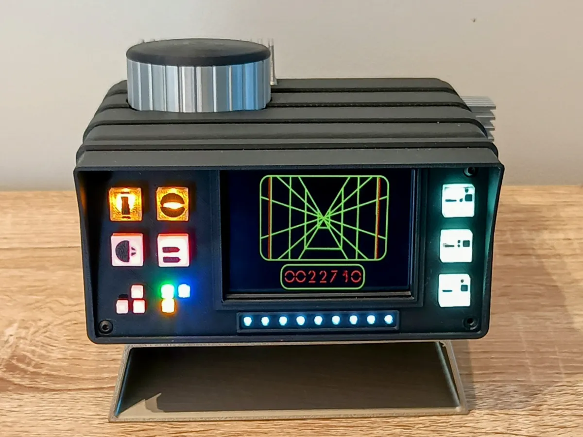
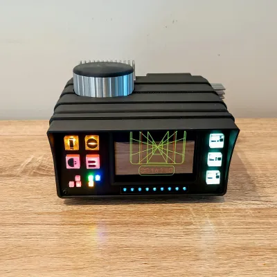
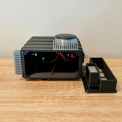
This project recreates Luke Skywalker’s X-Wing targeting computer from the iconic Death Star trench run scene in Star Wars: A New Hope.
The prop features a looping trench run targeting display, illuminated control panel LEDs, and optional sound, recreating the look of the targeting computer seen inside Luke’s X-Wing cockpit during the final attack on the Death Star.
This isn’t meant to be a 100% screen-accurate replica of Luke Skywalker’s X-Wing Targeting Computer from Star Wars: A New Hope. There are actually two pretty distinct versions seen in the scene — the physical prop itself, and the version shown with the screen, buttons, and lights. Trying to combine both into one small desktop unit didn’t really work the way I wanted, so I ended up taking a more inspired-by approach instead.
I wanted this to still feel recognisable and fit the Star Wars look, while also working as a compact display piece. I also took a bit of inspiration from the X-Wing Targeting Computer card art from the Star Wars TCG, which helped shape some of the design choices.
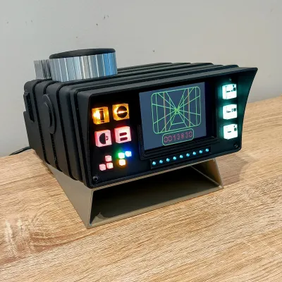
So while it’s not a perfect one-to-one replica, it’s my own take on the targeting computer that blends elements from the different versions into something I think looks right at home on a desk or display shelf.
The system is powered by a Raspberry Pi 3B, which automatically boots and launches the fullscreen video display when powered on. Once assembled, the targeting computer acts as a standalone sci-fi display piece perfect for desks, shelves, or Star Wars collections.
Features
• Looping Death Star trench run targeting display
• Screen inspired control panel layout
• Multiple LED indicator lights across the front panel
• Optional audio with adjustable volume
• Powered by Raspberry Pi 3B
• Automatically boots straight into the video display
• Designed for a 3.5" HDMI screen
Clear/Transparent Filament
Unfortuneatly Bambu Lab doesn't make a clear filament, I used Clear Transparent PLA filament from Sunlu using the Bambu Lab Translucent PLA preset. But any clear filament should do fine as long as you change the preset to the correct filament you are using
Assembly Instructions
Pi Setup Guide and video file in zip file in the Documentation section
1. Prepare the Raspberry Pi
Start by setting up the Raspberry Pi following the Pi Setup Guide included in this project.
Once the system is confirmed working and the video is looping correctly:
• Power off the Raspberry Pi
• Disconnect the HDMI screen
• Remove the Pi from the setup area
2. Prepare the Power Cable
You will need a short micro-USB plug for the Raspberry Pi.
⚠️ Important:
A normal USB cable or long micro-USB connector will not fit inside the body of the model.
I recommend using a short micro-USB plug and soldering wires directly to it.
- Solder approximately 300mm of wire to the V (5V) and G (Ground) pins on the micro-USB plug.
- Plug the micro-USB connector into the Raspberry Pi.
3. Optional Audio Wiring
If you plan to add sound, this is the best time to install the audio wires.
The best audio quality comes from the analog audio output pins underneath the Raspberry Pi.
You can solder wires, approx 300mm, directly to the left audio output, PP25, Red Wire, and ground, Black Wire, PP6 pads underneath the board.

You may also be able to find a short 3.5mm audio jack, but when I searched I could not find one small enough to fit inside the body.
⚠️ Note
I experimented with audio through GPIO PWM pins, but the result was very poor with high-pitched noise and screeching sounds. I strongly recommend using the analog audio output instead.
Tip:
Label the audio wires with a small piece of tape so you do not mix them up later. Once the Pi is installed it becomes difficult to trace the wiring.
4. Mount the Raspberry Pi
Attach the Raspberry Pi to the Pi Mount Plate using:
• 4 × M2.5 × 5mm screws
Orientation
The Raspberry Pi mounting holes are slightly offset to one side.
Install the Pi so that:
The HDMI port faces the side of the mount plate with the most open space (the side where the mounting holes are furthest from the edge).
This ensures the HDMI plug has enough clearance inside the body.
5. Install the Screen
- Attach the HDMI screen to the GPIO pins
- Connect the HDMI adapter to the Raspberry Pi and Screen.
The screen PCB will sit snugly against the mounting plate.
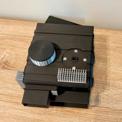
6. Install the Front LEDs
Install the following pre-wired LEDs in the front panel.
LED Layout:
• 9 × 3mm White
• 3 × 3mm Red
• 1 × 3mm Yellow
• 1 × 3mm Green
• 1 × 3mm Blue
• 3 × 5mm White
• 2 × 5mm Red
• 2 × 5mm Yellow

Follow the reference photos and LED layout chart for correct positioning.
To secure the LEDs:
- Insert each LED into its hole.
- Apply a small drop of CA glue to hold it in place.
7. Organise the LED Wiring
To keep wiring manageable, group the LEDs into the following four groups:
Group 1
• All 3mm white LEDs
Group 2
• The three 5mm white LEDs
Group 3
• The two 5mm yellow LEDs
• The two 5mm red LEDs
Group 4
• The three 3mm red LEDs
• The three coloured LEDs (yellow, green, blue)
For each group:
- Strip the wire ends.
- Twist together all red wires from that group.
- Add an additional 300mm red extension wire.
- Solder and tin the connection.
Repeat the same process for the black wires.
Repeat this process for all four LED groups.
8. Install the Pi Assembly Into the Body
Insert the Raspberry Pi assembly into the front body.
Orientation:
• The HDMI plug should face downward, toward the side with the white 3mm LEDs.
Slide the screen into the mid body section.
The screen should fit snugly against the inside edges of the body.
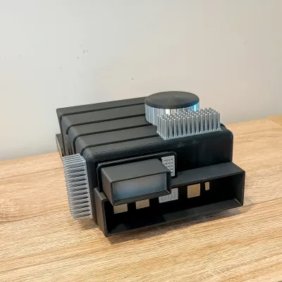
Targeting Computer orientation:
• The hump is the bottom
• The round cut-out section is the top
Insert front plate into mid body and secure the assembly using:
• 4 × M3 × 12mm screws
Tighten firmly, but do not overtighten to avoid stripping the plastic.
9. Installing Audio (Optional)
If you are adding audio,
First prepare the PAM amplifier board.
Solder wires to:
• 5V
• GND
• Left Output +
• Left Output –
Next join the speaker wires to the amplifier output wires.
• Left Output + to Red Speaker wire
• Left Output – to Black Speaker wire
Now install the speaker into the body.
Place the speaker into the recessed speaker area inside the body.
Secure the speaker using either:
• M2.5 screws
• A small amount of glue
Make sure the speaker is seated correctly and facing outward through the speaker hole.
Next connect the Raspberry Pi audio wires to the amplifier.
Connect the wires from the Raspberry Pi to:
• Red Wire from PP25 to Left Input
• Black Wire from PP6 to Ground
Insert the amplifier board into the recessed mounting pocket in the body.
The volume knob should pass through the hole in the case.
Secure the board with the provided nut.
Ensure the knob can turn freely.
You can now install the printed volume knob.
10. Install Switch
- Solder two red wires to the switch.
- Insert the switch into the slot on top of the body.
11. Install Magnets
Install the magnets into:
• The top section of the body
• The silver top cylinder component
⚠️ Important
Check the magnet polarity before gluing.
Once confirmed, glue the black top cylinder piece onto the silver section.
12. Final Wiring
Take the following black wires:
• The four LED group grounds
• The Raspberry Pi USB ground
• The amplifier ground (if used)
• One additional black wire
Twist, solder, and cover with heat shrink.
Repeat the same process for the red wires:
• LED power wires
• Raspberry Pi power wire
• Amplifier power wire (if used)
• One wire from the switch
Finally:
• Insert USB cable into mid body from the under side
• Connect the remaining red switch wire and addtional black ground wire to the USB Cable
13. Add Strain Relief
Add strain relief to the USB cable where it enters the body, I insert the USB cable into the mid body approx 10 to 20mm and add some hot glue around the cable and hole.
14. Test the System
Before closing the body:
- Connect power.
- Confirm the Raspberry Pi boots.
- Confirm the video loops correctly.
- Confirm LEDs and audio are working.
Fix any wiring issues now before continuing.
15. Assemble the Rear Body
Glue the following parts into the rear body section:
• Silver parts
• Gold Iridium parts
• Transparent Flash Lens
For the flash lens:
Install it with the textured print-bed side facing outward.
16. Final Body Assembly
- Insert the alignment pin into the mid body.
- Glue the rear body section onto the mid body.
Orientation:
• The flash lens should be at the top.
17. Install the Seam Hider
Glue the seam hider ring around the mid-body/rear-body seam.
This part:
• Hides the seam
• Helps disguise any minor warping from large flat prints
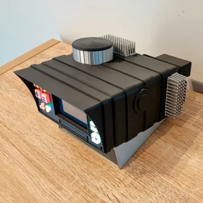
18. Install Heatsinks
Glue the decorative heatsinks onto the body.
19. Install Buttons/LED Covers
Glue the Buttons/LED Covers with a few drops of CA glue following this layout.

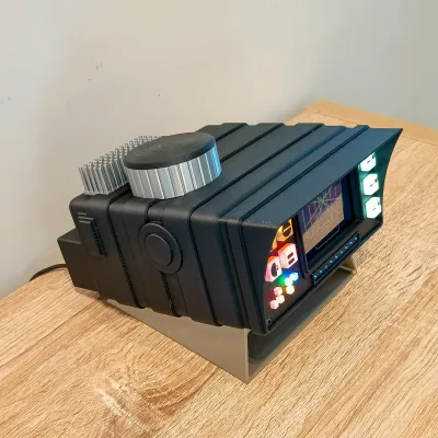
Finished
Put it in the stand, power it on, let the display spring to life, and enjoy your own little piece of X-Wing tech on the desk.
Just remember to stay on target and launch your ion torpedoes
Originality of the Model
The author declares that this work is their personally original model
This model is licensed under the following terms:
This work is licensed under a Standard Digital File License. Digital files have a strict non-commercial, personal use only license.
You shall not share, sub-license, sell, rent, host, transfer, or distribute in any way the digital file or 3D printed versions of this object, nor any other derivative work of this object in its digital or physical format (including remixes of this object). You can not host these files on other digital platforms, web stores or cloud repositories. The objects may not be used in any way whatsoever in which you charge money, collect fees.
Models(1)
- Star+Wars+X-Wing+Targeting+Computer.3mfDesigner

71.41 MB

2026-06-04
Attachments(2)
pdf
X-Wing Targeting Computer Bill of Materials (BOM) (1).pdf
107.10 KB
2026-06-04
zip
Targeting Computer (1).zip
23.26 MB
2026-06-04