












Print bed heater circuit board
Centauri Carbon
Elegoo Centauri Carbon
LED display stand

- 0.2 mm layer height, 2 walls, 10% infill

10-disc
PETG
Designer

1k

49
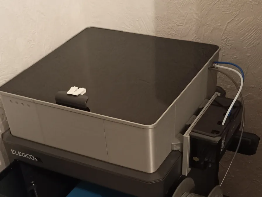
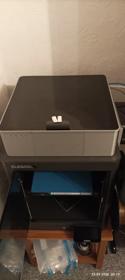
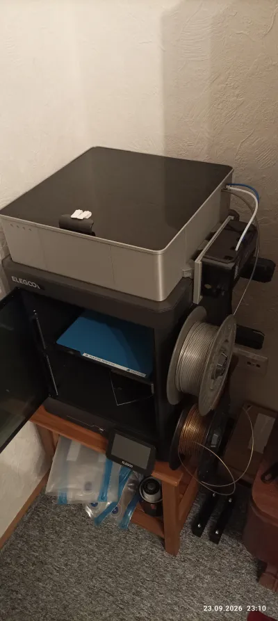
Riser to go on top of a Elegoo Centauri Carbon (1) for use with the CANVAS system.
This is my own design yet it is heavily influenced by the design here curtesy of AL-ExtremeError that aims to serve the same purpose and which i partialy printed previously just to find that it does not work well for me.
My design addresses several gripes that i had with the linked design:
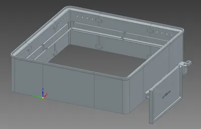
- corner pieces have been reworked to be universal for each corner this means that the holes for the Filament inlets are present in all corners and on both sides of the L-shaped corner piece. They are capped by default with a thin (2mm) wall towards the outside that shall be drilled out by the user for usage where required
- the parts are designed with uniform tickness all around – this means settling for 10mm everywhere as that is the thickness that works for the front side of the printer.
- all frame parts are designed to be printable without supports and in natural orientation.
- most parts are designed with molded in labelling to ease assembly
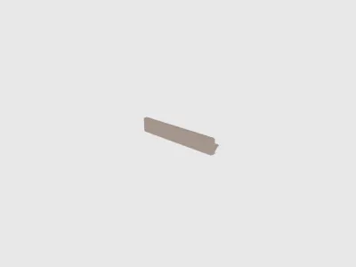
- instead of the individual parts connecting with dovetail joints which are hard to get right tolerance-wise and that could render the entire thing basically unassemble-able this design uses structural beams that connect using selftappers the holes for which are baked into the model. so that there is no guess work as to their placement. The structural beams double as a carrier bracket for standard 9mm LED Tape. there may be a need for additional glue for the tape to stay put in place!
- for the getting the structural beams in place there is an alignment edge where the upper edge of the beam will rest against. putting in the screws first and letting them protrude by ~1-2mm eases with alignment.
- the combination beams are intended to print backside down with no supports.
- all inside facing (ie aestethically non critical) corners are rounded over to ease with printability in the natural orientation.
- There is precisely one variant instead of several to choose from which greatly simplifies selection of the applicable models to print
slight differences w/ the size of the top glass between printers may be accomodated w/ simple scaling of the center pieces. for me the riser came out tight fairly tight but managable.
Since the pieces do not connect together w/ dovetail joints as in AL-ExtremeError's design the riser is susceptible to twisting in that when you hold the corner and try to rotate the center pieces this is possible in small degrees (literally). I mitigated this by adding in some connecting plates that are screwed into place (due to their reduced thickness using shorter screws). The overall flex this allows also comes in favor for my rather tight fitting top glass… (your mileage will vary)
for printing i recommend to go w/ PETG, I used the textured PEI plate with honeycomb infill for large flat parts and LARGE mouseears for additional bed adhesion (for slim parts) which worked way better than my previous attempts with the linked model that where printed on a cryogrip plate with no adheasion means at all (but also with rectilinear infill and no corner round overs all of which likely contributed to my warping problems).
There is explicitly no LED connecting piece included to replace the existing lighting as any LEDs may also be supplied indepentantly via external supplies getting which to the LEDs is easily doable by using the plentiful inlets for the filament.
note that there will be seams between the individual components of the riser that (depending on color choice) will be more or less visible but that most definitely are not air tight.
If you print a lot with styrene-based filaments or other nasty filaments and these creeks bother you or if they just bother you visually i found that putting some tape over them at the very least mitigates the latter provided the tape has an appealing contrast color to the rest of the print. For me having printed this in concrete-gray i found thin strips of EMC shielding copper tape to be attractive.
I strongly advise against randomized z-seam on this print for aesthetics (I tried, does not look good).
The holes in the combination beams in the recommended orientation will most likely come out smaller than designed. My common approach is to design in 2mm holes for my 2mm selftappers rely on the fact that they come out useable in z-direction and all holes printed in the xy-plane i drill out w/ a 2mm drillbit that just so happens to be a bit undersized… do your own experiments there.
For my print I printed just about everything individually:
- the corners i printed two of at the same time successfully (except i screwed up and produced an earlier revision where the inlet port holes are also available on the outside),
- the center pieces were exclusively printed individually
- the combination beams I attempted to print 4 at a time and the retractions for the labelling clogged the nozzle – going with one at a time works ok so i did that ultimately.
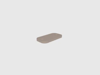
- the connecting plates to get the twisting somewhat under control are an afterthought that for my depicted print I just created by chopping up some templates I made for the corner and center pieces and screwing those in – the design files are updated to have proper connecting plates.
With a print like this one should definitely expect that things will go wrong in various places so even though the print is well under 1kg (2.2lb) I suggest getting yourself 2 or even 3kg of material to have enough margin of error. Going with B-Grade material (as I did) totally works if you get enough material of the same color (unless multicolored is intentional)
Also anticipate this to be a print that can take ~20h of pure printing time with conservative profiles (which i went for). Even swtiching to the “Ludicrous” setting on the printer during print – while working – does not significantly change this; you maybe save 2-4h. With everything being screwed in place you will need a lot of screws (comparatively speaking)!
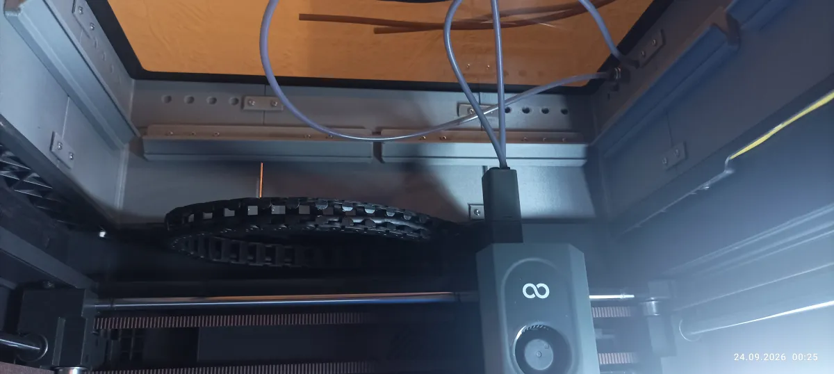
for getting filament in and out standard fittings are used – at design time i went w/ the PC4-M6 variant with the holes' design diameter being 5.5mm to allow for the threads to have material to grab (i did not have sufficently many of those and getting them in the material is not easy either; i then switched over to PC4-M10 which fit by drilling out the holes with a 8mm drill bit (so way undersize) and turning them in w/ a cordless drill (effectively melting them in) (Note: the images show the riser w/ incomplete amount of PTFE Tube couplings but otherwise functionally complete)
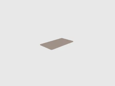
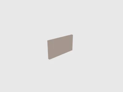
The CANVAS system is mounted similar to AL-ExtremeError's design w/ a backplate that slots into a retainment slot these slots have seperate holders that screw into the right center piece.
The difference being them being connected to the rim bridgers to fill the gap. you are intended to mount these first to the centerpiece and then the CANVAS slot afterwards to that.
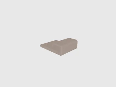
The design includes a cable clip for holding the CANVAS cable in place (also an idea inspired by AL-ExtremeError) except my cable clip bolts onto a rim bridger.
In the end I did not need that b/c the CANVAS cable was barely long enough anyways, mostly due to it being not angled as it should be as per the video install instructions. There are no predesigned mounting holes for that in the corner piece so you can mount it where ever – I did not install mine.
for detailed assembly instructions there is an assembly drawing available
Bill of materials
- NameQuantityNotes
- 12x10x4mm selftappers (shaftdia x lenght x headdia)61when going with the full 3 screws per side on each beam. going with one may suffice too greatly reducing the number of screws needed.
- 22x5x4mm selftappers (shaftdia x lenght x headdia)32for the connecting plates to get the twistyness under control
- 3tape or alike for covering up seams1amount dependent on user choice and other factors (optional)
- 49mm LED tape1optional, length not measured 3m (~9ft) should be plenty
- 5PTFE Tube fittings4design intend is PC4-M6 larger ones also work when the holes are drilled out more.
Originality of the Model
The author declares that this work is their personally original model
This model is licensed under the following terms:
Credit must be given to the creator
Only noncommercial uses of the work are permitted
Remixes must be shared under the same license
Models(10)
 cable clip.stlDesigner
267.76 KB

2026-09-24
 CANVAS plate.stlDesigner
394.71 KB
2026-09-24
- CANVAS Riser.3mfDesigner
3.65 MB
2026-09-24
 canvas slot.stlDesigner
364.54 KB
2026-09-24
 combination beam.stlDesigner
603.99 KB
2026-09-24
 connecting rod.stlDesigner
53.21 KB
2026-09-24
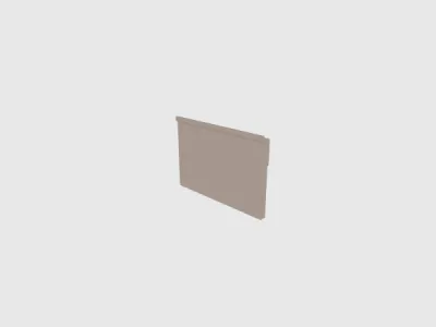 long center piece.stlDesigner
887.78 KB
2026-09-24
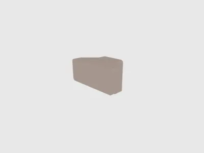 rim bridger.stlDesigner
270.79 KB
2026-09-24
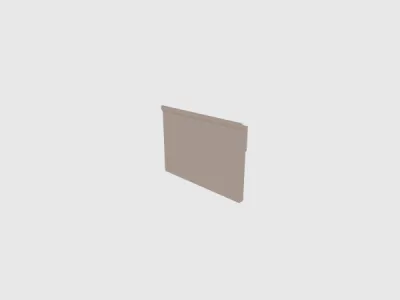 short center piece.stlDesigner
837.19 KB
2026-09-24
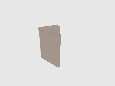 universal corner.stlDesigner
1.24 MB
2026-09-24
View all(10)
Attachments(3)
pdf
assembly.pdf
46.07 KB
2026-09-24
pdf
canvas.pdf
44.76 KB
2026-09-24
zip
Design files.zip
3.41 MB
2026-09-24
View all(3)


