


pcb
holder
stand
circuitboard
electronics
hold
soldering
solder
heat gun


111

5
Key Features:
- Large jaw size: 130mm width max.
- Reflow oven and hot air rework compatible* (Only as heat resistant as the materials you choose to use. If you're using this in a reflow oven, make sure the grips, bearings and glue can withstand the heat)
- Customizable jaws: STEP file provided for modifications if special holders are needed for dedicated PCBs or ICs.
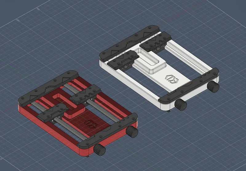
- Two variations, CNC and 3DP.
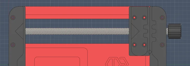
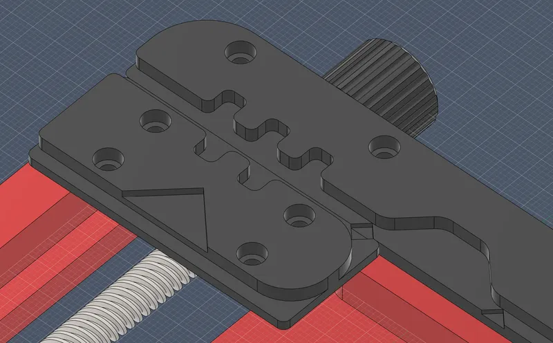
- 2 BGA IC holders included for 17.5mm+ ICs and two smaller IC holders for 3.7mm+. These IC holders can be repurposed to hold pcbs at a 45 degree angle.
- Uneven holder: Use two of the jaws and the edge grip to hold non-rectangular PCBs. the curved grips are designed to fit a wide range of PCBs of unusual shapes, such as circular, or polygonal or wavy.
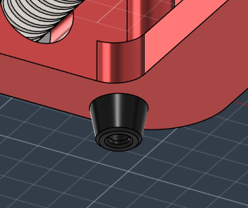
- Non-slip feet: Can be printed with TPU. Do not include if using in a reflow oven. You can also manufacture these in a high temperature rubber or silicone.
- Comfortable textured hand grips.
- Channel for larger pcbs with large components or header pins that may interfere with being inserted properly. Useful for dual sided PCBs where one side could have large transformers or electrolytic capacitors. The gaps below the lead screw also accomodates for specialised PCBs.
- Built to last: Rigid design that can last a lifetime, especially if ordered out of metal from Justway.
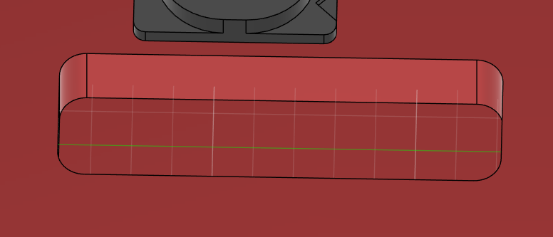
- Emergency strorage hole: Primarily there to reduce weight but also doubles up as a place to dump parts. I also like to cut up a soldering sponge and place a strip in here with a little bit of water. It makes a suprisingly convenient tip cleaner.
- The jaws are made from SLS nylon rather than aluminium due to the intricacy needed, but also as pcbs can wear away the annodizing coating rather quickly, as the fibreglass is somewhat abbrasive. Additionally, nylon is softer than aluminium (duh) so it will have more gentle contact, preventing damage to the PCB sides and does not damage edge plating.
Hardware:
M3*25 Hex socket machine screws x4 (if not using TPU feet, replace these with four M3*6 screws)
M3*15 Hex socket machine screws x4
M3*6 Hex socket machine screws x12
M3*4 Heatset insert x32 (only if using 3D printed version. 8 inserts at the bottom can be omitted entirely.)
OD:12mm, ID:8, W: 3.5 Bearing x4
T8 Lead screw 200mm x2
T8 Lead nut x2 (one with two nuts. Make sure the threads on your nut matches the ones on the screw. I use “Tr8x8” with 4 starts. Do not cheap out on these nuts! cheap ones have a lot of slop, and ive needed to replace these twice until the majority of the wobble was gone)
(Also some high temperature epoxy or glue. Strong thermal glue designed for heatsinks also works, and is quite cheap. You most likely already have some. (If you are 3D Printing this model or not planning on using it with a reflow oven, regular glue is fine too.))
Assembly:
0. Prepare parts by 3D Printing, ordering, CNCing, etc. Thread, or Insert heatset inserts if needed
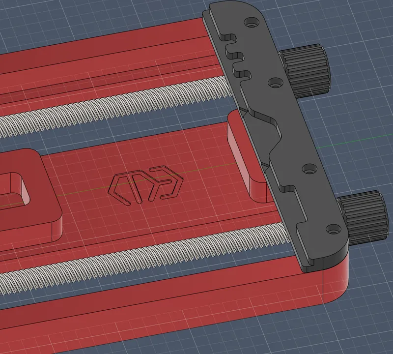
- Install 4 bearings in to the base. Make sure they are flush with the outside. Use glue to keep them in place. I suggest putting the glue on the base first then pushing the bearing in, that way excess glue is pushed to the inner side where it is harder to see.
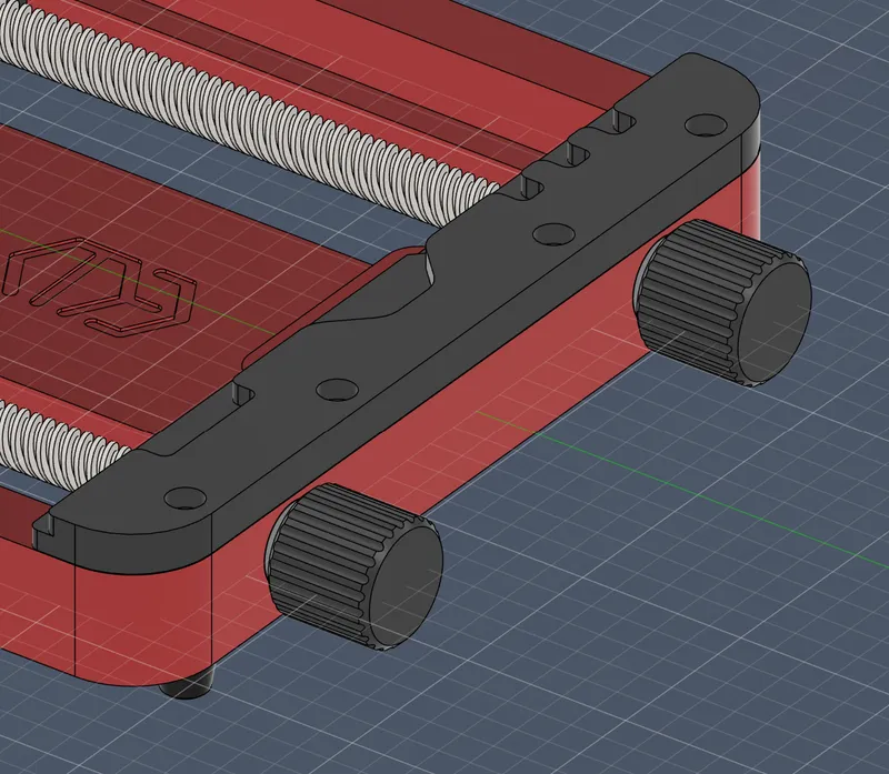
- Attach the knobs to the T8 lead screw with some glue. Let set
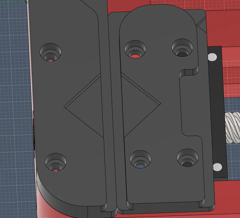
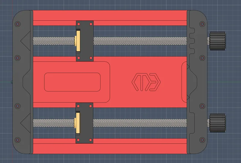
- While that cures, Use 4 M3*15 screws to attach the lead nut to the carriage blocks.
- Using the 12 M3*6 screws, attach all of the jaws (grips) as following. Orientation of the carriage blocks doesn't matter. This holder can be assembled in multiple configurations. The knobs can face to the left or right too based on preference. If you are using TPU feet, use 4 M3*25 screws in the corners.
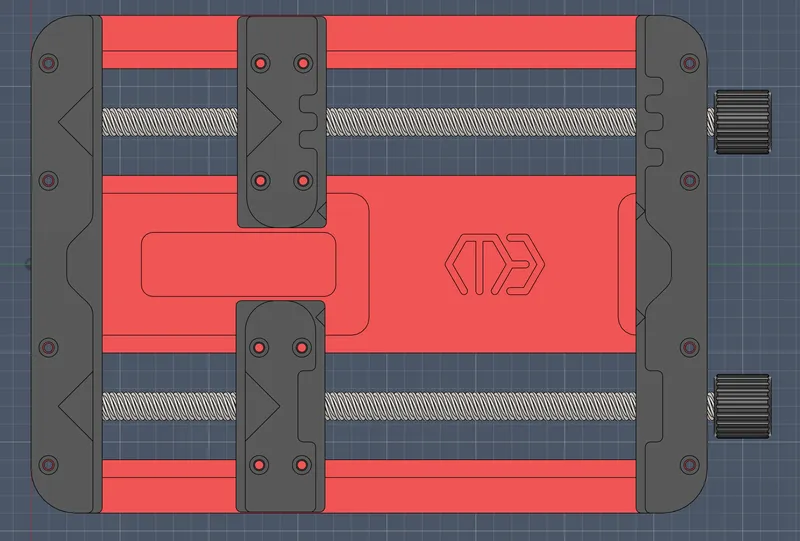
- Insert the lead screw through the bearings and through the carriage block. Check the fit and see if everything is as expected. Slide the lead screw out by 1 or 2 cm and apply glue where the lead screw will come in to contact with the bearing. Push in and let cure. Make sure glue doesnt enter the bearing, or sieze movement. Let set.
- Flip the holder over and add the TPU feet on the exposed threads from the M3*25 screws in the corners.
- The holder is done. Enjoy!
Miscellaneous
The holes in the CNC cad model are not threaded and are at 2.529mm in diameter (because Fusion is weird). You can thread these yourself to M3 or ask the manufacturer (Justway) to just do that for you.
I have provided .STEP files for your editing. You can edit or make your own grips or remove my logo if you'd like, I don't mind
On the 3D Printing version, the carriage blocks should be printed upside down (the side with the 4 heatset inserts should be placed on the bed)
This probably goes without saying, but in my CNC version, not all parts are for CNCing. The grips and knob are made with SLS 3D Printing. Please choose a high temp material for these. You can also order these to be 3D Printed from metal with MJF, SLM or similar. It is likely that these SLS parts will be your limiting components for temperature. Metal jaws will be more abbrasive and more likely to damage the PCB however. Maybe CNCing from a high temperature plastic is an option?
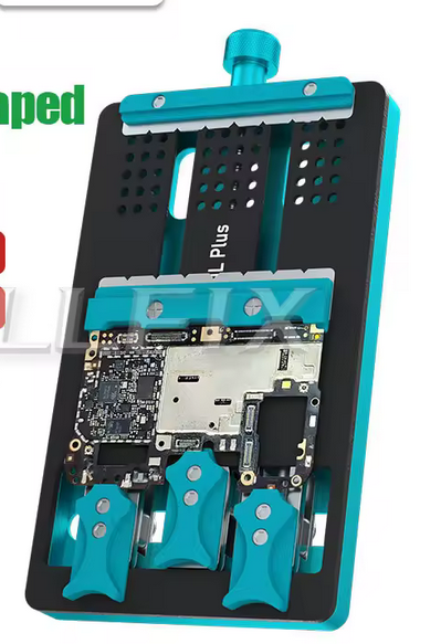
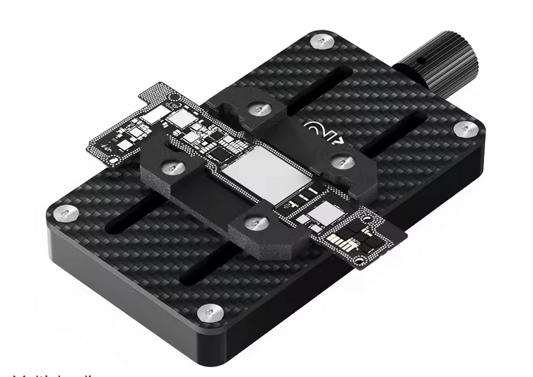
This project is inspired by PCB holders on aliexpress like these: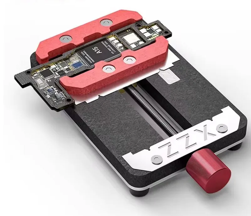
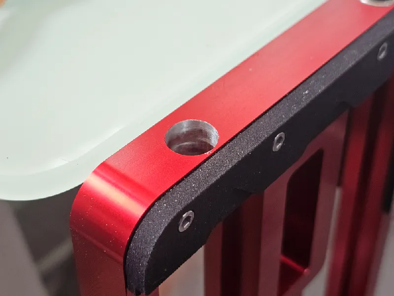
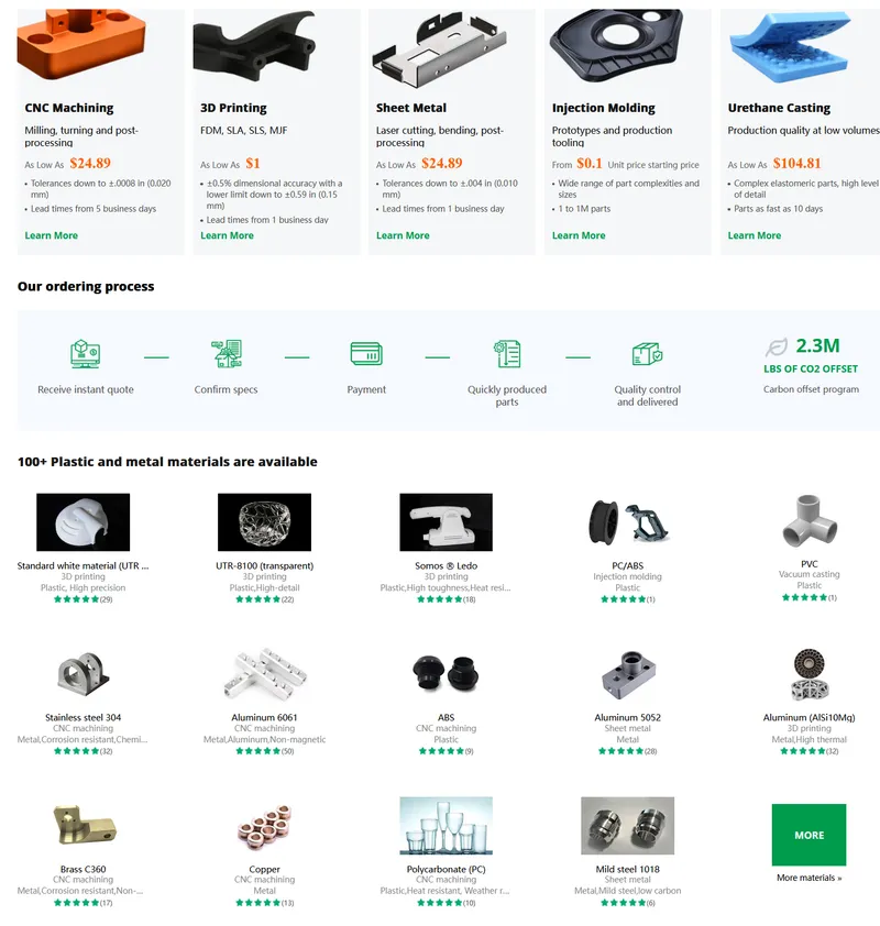
Thanks to JustWay for sponsoring this project! With 100+ different materials, they offer manufacturing services for quite a low cost without comprimising quality. I have been mostly pleased with the results especially with the part accuracy and annodisation of aluminium. The CNC parts are smooth without scuffs or gouges from manufacturing (although machining marks are visible). Their services include CNC machining, 3D Printing, Sheet metal fabrication, Injection moulding and Urethane casting. These are offered at small scales to large volume batch production.
With regards to product quality, the annodization was consistent, and no machining marks could be seen on the black parts. On the large red baseplate, machining marks are visible, but they are consistent, and appear like an intentional design. These CNC parts were pretty much perfect dimensionally, and the SLS parts were also well within manufacture tolerance.
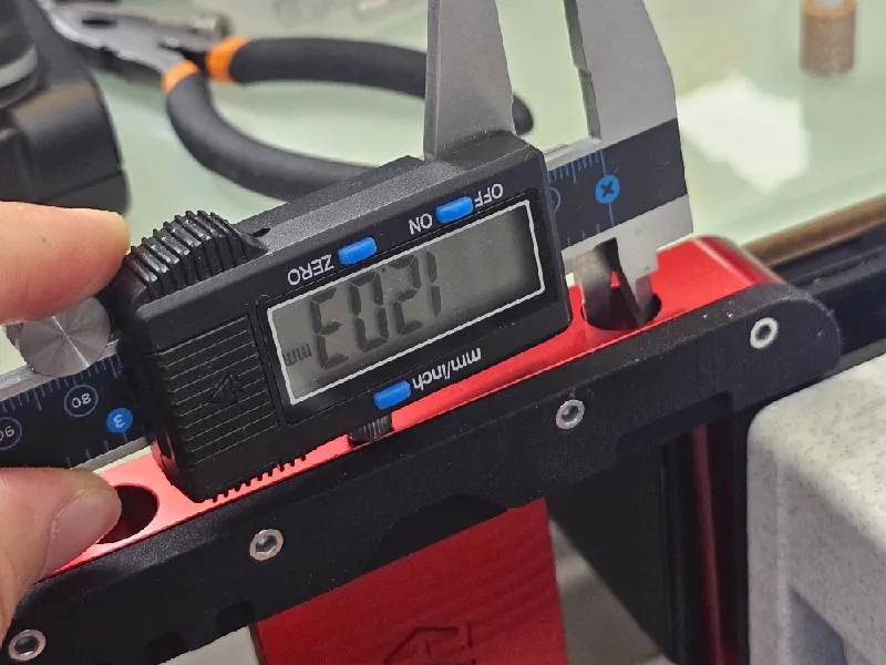
There was also one problem where my 12.2mm holes were reduced to 12.0mm in manufacturing. This resulted in my bearings not fitting, so I had to use a dremel to widen the hole. If you are ordering this from Justway, make sure to specifically and clearly state that you want the holes to be 12.2 (maybe 12.1mm) but not any smaller.
Sponsors like this keep my projects at a high quality and available for free to download! Please check out their capabilities and place your order here:
https://www.justway.com/
For a $5 discount on first orders, consider using the following affiliate link! https://justway.com/g/q5G5zP

Originality of the Model
The author declares that this work is their personally original model
This model is licensed under the following terms:
Credit must be given to the creator
Models(15)
 cnc_base.stlDesigner
12.94 MB

2025-09-01
 cnc_carriage.stlDesigner
5.91 MB
2025-09-01
 fdm_foot.stlDesigner
527.43 KB
2025-09-01
 sls_edgegripa.stlDesigner
2.96 MB
2025-09-01
 sls_edgegripb.stlDesigner
2.00 MB
2025-09-01
 sls_knob.stlDesigner
16.68 MB
2025-09-01
 sls_slidergripa.stlDesigner
2.09 MB
2025-09-01
 sls_slidergripb.stlDesigner
1.85 MB
2025-09-01
 fdm_base.stlDesigner
10.53 MB
2025-09-01
 fdm_carriage.stlDesigner
2.97 MB
2025-09-01
 fdm_edgegripa.stlDesigner
2.67 MB
2025-09-01
 fdm_edgegripb.stlDesigner
1.72 MB
2025-09-01
 fdm_knob.stlDesigner
16.68 MB
2025-09-01
 fdm_slidergripa.stlDesigner
2.04 MB
2025-09-01
 fdm_slidergripb.stlDesigner
1.80 MB
2025-09-01
View all(15)