




Desktop fixture
Electronic DIY tools
Mini bench vise
PCB repair fixture
Welding auxiliary fixture
Small clamp
Hand vise
Model clamping tool
- Layer height: 0.16 mm, wall thickness: 2 layers, infill density: 15%

1-disc
PLA
Designer

14

5
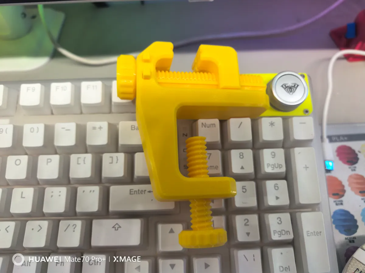
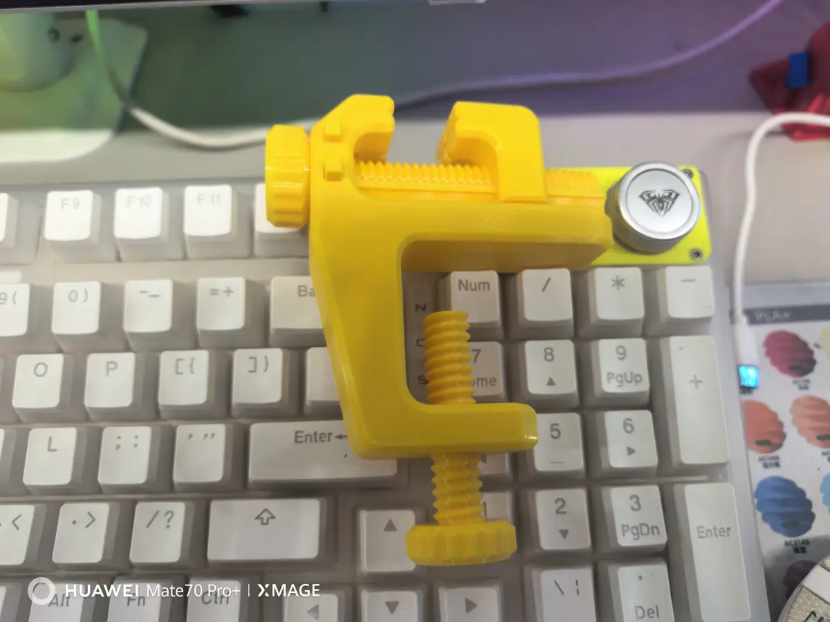
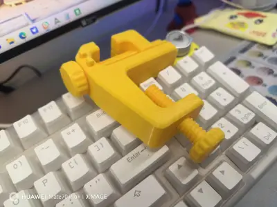
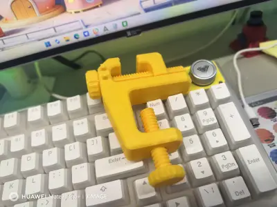
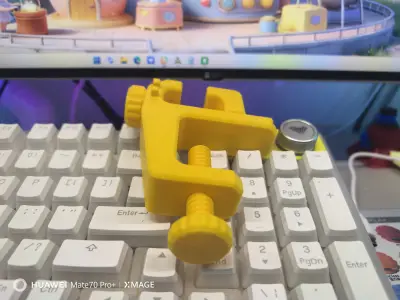
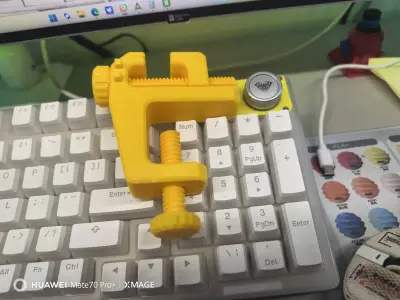
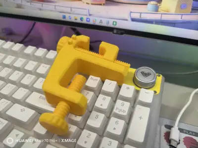
This desktop fixture features a classic C-shaped vise design with dual-threaded knobs, allowing simultaneous adjustment of vertical and front-to-back clamping. It’s compatible with a wide range of items, including PCB boards, small parts, and model components. After printing, it’s easy to assemble, delivers stable clamping force, and is an essential desktop tool for electronics repair and DIY projects.
🔧 Design Highlights
Two-way Adjustment: A main vertical screw combined with a fine-tuning knob for front-to-back movement enables precise control over the clamping position, preventing part displacement and ensuring unobstructed access during PCB soldering.
Non-slip Clamping Jaws: The jaws have been widened and thickened to increase contact area, providing secure grip on PCBs and small parts without slipping or damaging the workpiece.
Broad Compatibility: The maximum opening distance accommodates common PCB boards and model parts, and the fixture can be directly mounted on desks or workbenches.
Printer-Friendly Design: The modular construction eliminates complex supports; it can be printed using PLA or PLA+ filaments, making assembly straightforward even for beginners.
🖨️ Recommended Printing Parameters
| Parameter | Recommended Setting |
|---|---|
| Layer Height | 0.15–0.2 mm |
| Infill | 40%–60% (higher infill for tool-like parts to enhance structural strength and clamping force) |
| Wall Thickness | 2.0 mm (5 wall layers to improve resistance to compression) |
| Filament | PLA/PLA+ (PETG optional for enhanced durability and heat resistance to prevent warping) |
| Supports | Only minimal supports are needed at threaded holes; the main body can be printed flat without additional support. |
📝 Assembly & Usage Instructions
After printing, remove burrs and any remaining support material from the threads and clamping jaws to ensure smooth rotation of the screws.
Screw the upper and lower screws into their respective threaded holes and test the knobs to confirm smooth, free movement without jamming.
When in use, first secure the fixture to the edge of the desk, then place the PCB or part to be processed in the clamping jaws. Tighten the upper and lower as well as the front-to-back knobs to adjust the clamp to the desired position.
During soldering or repair, place a small piece of high-temperature-resistant tape under the clamping jaws to prevent scratching the part or PCB board.
Originality of the Model
The author declares that this work is their personally original model
This model is licensed under the following terms:
This work is licensed under a Standard Digital File License. Digital files have a strict non-commercial, personal use only license.
You shall not share, sub-license, sell, rent, host, transfer, or distribute in any way the digital file or 3D printed versions of this object, nor any other derivative work of this object in its digital or physical format (including remixes of this object). You can not host these files on other digital platforms, web stores or cloud repositories. The objects may not be used in any way whatsoever in which you charge money, collect fees.
Models(2)
- 台钳1.3mfDesigner

1.24 MB

2026-05-02
 台钳.3mfDesigner
1.48 MB
2026-05-02


