




nerf

- Compatible with speeds of 80–90 mm/s; in actual testing, the speed reduction is only 6 m/s.

1-disc
PLA
Designer

13

1

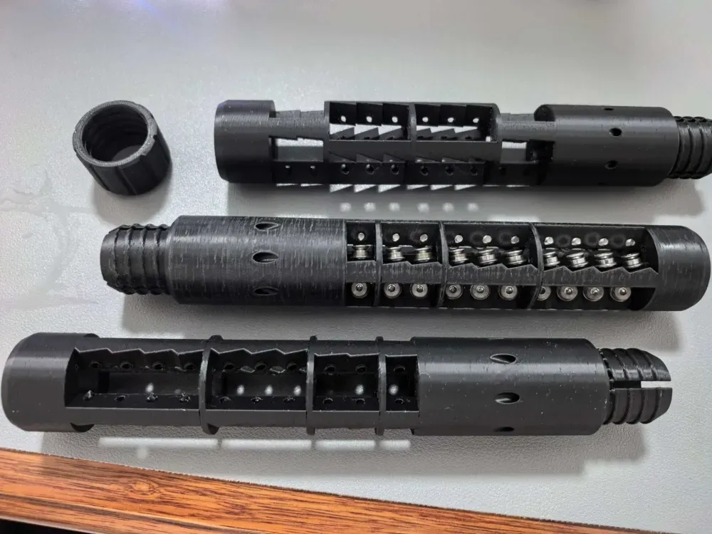
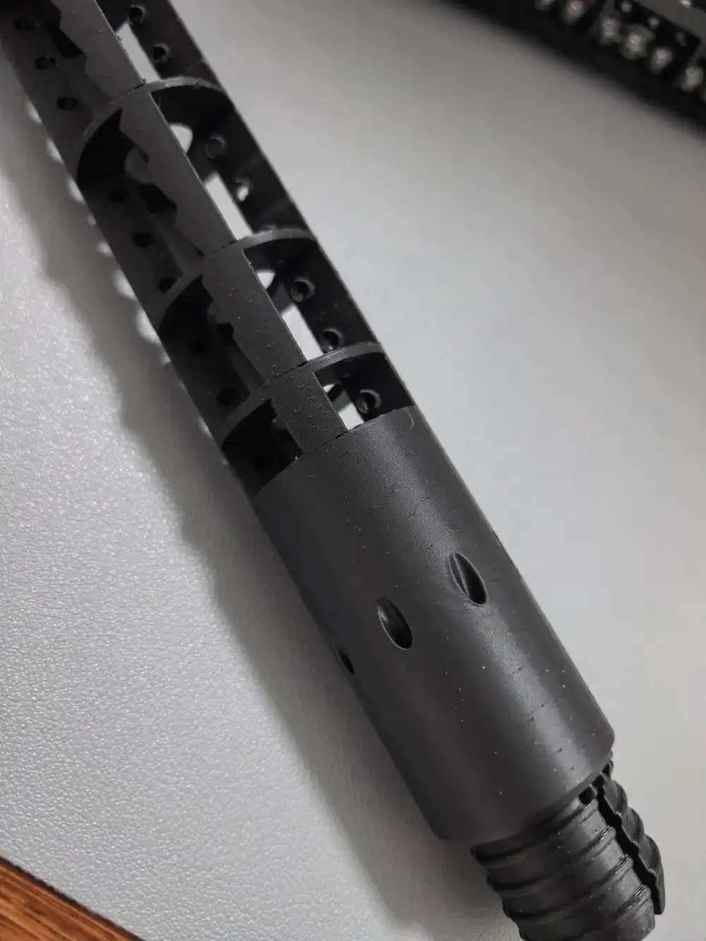
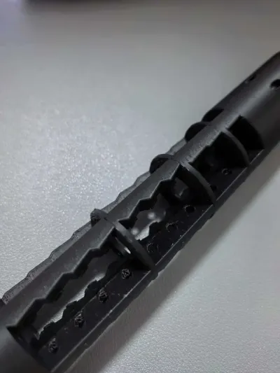
This is an ultra‑high‑freedom four‑zone angular bearing tube, featuring venting zones, hard‑raised threads, and four adjustable bearing sections that allow you to modify thread count, layer count, and angle settings.
In theory, you can customize it yourself to suit your desired bearing model (based on the maximum outer diameter of your bearings) and screw type. However, you’ll need to experiment—currently, I’m using MF63zz bearings paired with M3×8 countersunk screws, and the model’s default settings are tailored for these specific components.
For a more convenient way to tailor parameters to your needs, simply feed the details to an AI by clicking the link:https://chat.deepseek.com/share/djajwhqsm8c7pfm4r6
Here’s how to phrase your request:
“I currently use a launcher that achieves an initial velocity of 69 m/s ± 5 using a 1‑gram sponge soft projectile. If I were to use this model, what should be the angle, penetration depth, thread count, and layer count for each zone? How much clearance should there be between segments? And what settings would be optimal for the stabilization zone and pre‑rotation zone?”
After receiving the AI-generated parameters, double-check them against your specific requirements to avoid any unintended inaccuracies.


You can download the F3D file and manually adjust the settings to best suit your preferences, or search for “Sure Bearing Tube” on a third-party website (depending on your desired muzzle velocity).
1. Hardware specifications you wish to configure: inner and outer diameters of the main body, diameter of pins or screws used, and bearing diameter.
2. Chamfering of venting zones, venting channel angles, and venting channel aperture sizes.
3. Length and helix angle of the spiral section.
4. Four angular bearing zones, with separate adjustments for thread count, layer count, penetration depth, and shaft height based on the selected bearing type.
5. Thickness of partition plates separating each bearing zone.
6. Length and chamfering of the exit zone (with potential future enhancements under consideration).
P.S.: This model will continue to receive new updates regularly.
Call for Improvement Suggestions in the Comments Section
V2 Version Update:
The Sure Bearing Tube isn’t just about adding spin to soft projectiles—it functions more like a complete projectile attitude management system. Each segment has clearly defined roles, seamlessly interconnected and sequentially linked.
Section 1 – Assembly Zone
Function: Pure structural fixation, without participating in ballistic performance. This serves as the design’s “interface layer,” which can theoretically be customized to suit your preferred mounting method.
It isolates the entire functional tube section from the launcher body, effectively preventing clamping stresses from transferring to the precision-bearing and spiraling sections.
If assembly stress causes even slight deformation in the functional tube, accuracy could be completely compromised.
Section 2 – Active Venting and Flow‑Correction Zone
Function: Before the projectile enters the spinning section, cleanly expel high‑pressure tail gases to eliminate airflow disturbances. When a soft projectile is propelled by compressed air, a high‑pressure zone forms behind its tail.
As soon as the projectile’s tail passes through the venting hole’s inner opening, the high‑pressure gas must be immediately discharged; otherwise, an internal “air cushion” forms, striking the tail and causing minor oscillations upon ejection.
The venting hole is tilted backward (the internal opening sits closer to the spiral section than the external one), creating an “induced suction effect”: when high‑pressure gas jets backward, a low‑pressure zone forms at the opening, actively drawing out residual turbulence within the tube like a vacuum pump. A dual‑row design increases effective exhaust windows, ensuring sufficient venting time across various muzzle velocities.
Consequence: If venting is insufficient, the projectile enters the threaded section with lingering gas turbulence, causing all subsequent spinning stages to operate in an unstable initial posture. The 10‑meter dispersion may expand by 2–3 times.
Section 3 – Pre‑Spinning Thread Section
Function: Corrects the projectile’s attitude and applies a very slight pre‑spin, paving the way for the bearing section.
Traditional PCAR tubes use threading simultaneously for both attitude correction and spin addition, typically at angles of 5°–8°. This generates significant sliding friction on the projectile’s surface. By relegating the threading function solely to attitude correction and minimal pre‑spin, the primary task of establishing rotation is handed over to the following rolling bearing section.
Consequence: Without a dedicated threading section, the projectile directly impacts the first bearing zone after exiting the smooth venting area, potentially carrying a slight misalignment. In such cases, the first bearing zone must handle both attitude correction and spin initiation, leading to concentrated pressure and increased risk of slippage.
Section 4 – First Bearing Zone
Function: At the lowest stress level, reliably initiate projectile rotation. This acts as the “entry buffer” for the entire bearing zone.
Its angle should be the smallest among all four zones, while its penetration depth is the greatest. This combination of a small angle and deep penetration aims to gently yet firmly establish the initial rotational trajectory on the projectile’s surface, leaving no room for slippage. Why is the first zone particularly sensitive to slippage? If the projectile fails to start rotating here, it becomes a “smoothbore projectile” heading straight into the second zone, where sudden application of rotational force can easily result in severe irregular deformation.
Layer allocation logic: Two layers for low‑speed rounds, three layers for heavy low‑velocity rounds. Heavier rounds have greater inertia, requiring longer contact periods to ensure reliable startup.
Section 5 – Inter‑Zone Spacers Between Bearings
Function: Allow the projectile to elastically recover between bearing zones, preventing continuous compression that leads to stress accumulation. Sponge is a viscoelastic material; after being squeezed by the bearings, it doesn’t rebound instantly but requires time to regain its original shape.
For example: Immediately after exiting the second zone, the projectile remains flattened, rushing straight into the third zone. There, the bearing exerts even greater pressure on an already deformed projectile, exponentially amplifying frictional forces. The inter‑zone spacer provides a “breathing window.” Here, the projectile is entirely free from bearing pressure, allowing the sponge to restore its roundness and prepare for the next bearing contact.
Section 6 – Second, Third, and Fourth Bearing Zones: Rotation Establishment and Final Shaping
The second zone serves as a transitional stage, taking over the initial rotation initiated in the first zone. Its angle and penetration depth gradually align with those of the main working zone. Its role is to ensure a smooth transition, helping the projectile adapt progressively to the upcoming rotational pressures.
The third zone is the main working zone—the heart of the entire bearing tube. It’s where the majority of the projectile’s rotational momentum is established.
The third zone is critical: too steep an angle results in excessive loss of initial velocity; too shallow a penetration depth leads to unreliable engagement and slippage; too few layers cause pressure concentration, making it impossible to distribute load evenly.
The fourth zone acts as a final shaping stage, slightly reducing the angle and gently lowering the penetration depth to perform last‑minute attitude corrections and roundness refinements on the completed rotation. Unlike the third zone, which aggressively pushes for additional spin, the fourth zone functions more like a finishing edge‑trimmer, ensuring the projectile exits the bearing zone in a symmetrical form.
Section 7 – Stabilization Zone
Function: With no pressure constraints, the sponge fully releases accumulated stress and regains perfect roundness, enabling the projectile to emerge in its most stable posture.
This is often misunderstood—initially, I worried that an overly long stabilization phase might dramatically increase friction. However, its positive threads run parallel to the axis rather than forming angled spirals. Extremely shallow penetration creates only a very light surface contact, exerting no rotational torque. After experiencing the most intense squeezing in the third zone, the projectile still carries residual internal stresses that require time to dissipate. If it were to exit the fourth zone directly, this “stress‑laden” projectile would exhibit irregular bounces during flight, significantly increasing dispersion. A prolonged stabilization phase essentially provides the projectile with a pressure‑free recovery chamber, ensuring that by the time it emerges, it has already undergone “cold‑shaping” and achieved a cylindrical form with minimal aerodynamic drag and maximum flight stability. For high‑speed applications, an extended stabilization period is recommended: the higher the velocity, the shorter the recovery time. For instance, at 100 m/s, a 75 mm stabilization ring offers only 0.75 ms of recovery time—not a waste of length, but a necessary measure.
Bill of materials
- NameQuantityNotes
- 1带挡边的微型轴承、沉头螺丝36轴承和螺丝型号可自行选择
Originality of the Model
The author declares that this work is their personally original model
This model is licensed under the following terms:
This work is licensed under a Standard Digital File License. Digital files have a strict non-commercial, personal use only license.
You shall not share, sub-license, sell, rent, host, transfer, or distribute in any way the digital file or 3D printed versions of this object, nor any other derivative work of this object in its digital or physical format (including remixes of this object). You can not host these files on other digital platforms, web stores or cloud repositories. The objects may not be used in any way whatsoever in which you charge money, collect fees.
Models(2)
 Sure轴承管V2全功能.f3dDesigner
1.54 MB

2026-05-19
- Sure轴承管V2_80_90_1.1_1.2.3mfDesigner
2.26 MB
2026-05-19


